


DomC
-
Posts
605 -
Joined
-
Last visited
Content Type
Profiles
Forums
Events
Articles
Marionette
Store
Posts posted by DomC
-
-
vs.ResetObject() actually regenerates the pio and change the geometry after with vs.SetRField() parameters are changed and I tried also 1167. The specific thing here is, that the cabinet contains also plugins (Custom Parts) which maybe are not reseted as expected and the additional relations of fittings interact with the parts and not directly with the cabinet maybe. I will give accessing the sub-pios of the cabinet and if that not will not be of use i will wait for another solution.
Already I am in contact with the genius devs from extragroup but there are always some other more important tasks to address so I wondered if i could bypass this limitation on the script-side.
-
Thank you for that feedback Hippocode and JBenghiat.
Of course you are absolutely right. I should have been more specific about what I'm trying to do in the first place. I have a script that reshapes interiorcad cabinets together with custom parts and milling pios which are attached to that objects.
Unfortunately, applying a vs.ResetObject() to these objects disconnect their connections to the fittings and other associated elements. The PIO itself runs a code, that is able (if nothing went wrong) to keep that relations.
So there are some options:
1. The developper of that PIOs implements an API which can be triggered by vs.ResetObject()
2. I find a way to fire the right events to that PIO so that it is forced to regenerate (It also has a button to update)
3. It is maybe a bug in the vs.ResetObject()
#1 is maybe the best option but if it can be controlled by the script itself it would be seen prefered.
Here what the script does. It is open source and addresses a very often mentioned requirement from customers.
-
Hello
The question is maybe naive. As I know, there are Events that happens while the usage or code-run of an object. As example 3 for reset, 5 initProberties etc. Is it possible at all, to fire such an event on a PIO from outside. Or trigger the PIO with something more controlled than vs.ResetObject()?
To be specific:
1. Fire a standard-Event like 3 (I think vs.ResetObject() does that) or 41 or 43?
2. Or a custom event. Lets say I have a button ID inside the PIO like:
(theEvent, theButton) = vs.vsoGetEventInfo( )
With simple words: Can I push the button from outside with something other than the Mouse cursor?
Thanks
DomC
-
Hi
I think this behavior was in SP2 or SP3. It is fixed for SP4. I guess you should download the Version new as an SP4 Version because maybe trial license can't be updated. -
Wow
You are my Hero. Thank you so much! Tool Type index 2 was the right joice. -
Hello
So far it works implementing a Tool in the Workspace and Creating a new Palette Group. So far it works for path Objects or Point Objects (vso). Event Enabled or not Event Enablet. But I can't get it to work with a VST. I tested with this tool "Blindfront" This one here:
As soon as I manually drag it into the workspace the tool works. and also after that the tool i added with the script works. So far the workspace itself looks identical if i drag manually the tool in the workspace as if i create the tool by script. I think I am missing some important parameter here.
The Tools is placed into the palette and is shown ad expected but not the tool can't be selected.
Anybody can help?
Here My small test:
#Get Group Palette by Index 1 (0 is Construction palette)
pName = vs.ws2GetToolAt("", 1)
result, outDisplayName, outShortcutKey, outShortcutKeyModifier, outResourceID = vs.ws2GetToolInfo(pName)

vs.AlrtDialog('Put Tool in ' + outDisplayName)

#The .vst is already in the Plug-Ins Folder

# id of group palette
tsPath = pName #outDisplayName#GetPalettePath('Werkzeuggruppen')

tsName = 'NewPalette'
tsNameUniversal = tsName #can be a uuid or just here for Testing 'NewPalette'
vs.ws2CreateToolSet(tsPath, tsNameUniversal, tsName, '')
path_new_tool = '/'.join([tsPath, tsNameUniversal])

# Add tools
ok = vs.ws2CreateTool(path_new_tool, "Blindfold", 3) #Don't know what this index 3 is used for

#vs.ws2GetToolInfo(toolPath)
vs.ws2CommitChanges(False, False)
bWorked = vs.wsEditEnd(False)
-
It looks for interaction with the VW API it would need a very different kind if integration of the python language or additional APIs which are able to communicate with the python script. Which maybe needed a very big effort or would not pay out the effort. I think the reason it not, that python can't pause.
If i draw an object and then get after that some informations from that object, somehow the object was created in Vectorworks (not drawn, but minimum defined). So The python script here waits for the Object created by the VW binary and so i think it could be possible the python script also can await the user interaction. So I guess it user interaction may be is not technically limited because of python itself.
-
Also tried to solve that issue. But without a big success. You can run the complete python as a callback of GetPt. But Nested callbacks are not possible. So just one click can be done.
My Workflow is to create a main script as a Vectorscript. I collect the clicks and user interaction and then run the python script inside this script. Also it is possible to run several python scripts inside the pascal wrapper. So far no better solution I can see.
It gets two clicks in the drawing and draw a preview rectangle. Then save the result in the value reprository, where the python script after that can load the data. It you want to pause somewhere your python script and make a user interaction this workflow is not possible.
Example for the Pasca-Script that calls the python script:
PROCEDURE Reshape;
VAR
	h1, h2, h3 :HANDLE;
	scriptName, values2python : STRING;
	py, res: BOOLEAN;
	s: DYNARRAY OF CHAR;
	pt1, pt2 : POINT;
	pt, pt_tl, pt_br : POINT;
	plan_rotation : REAL;


 FUNCTION TempToolCallback(action, msg1, msg2 : LONGINT) : LONGINT;

    BEGIN
         TempToolCallback := 0;
         CASE action OF
             3: BEGIN {kOnToolDoSetupEventID}
		             vstSetHelpString ( 'definiere rechteckigen Umformbereich auf' );
             END;

             103 : BEGIN {kToolDrawEventID}
                 vstGetCurrPt2D( pt.x, pt.y );

                 pt_tl.x := Min(pt.x, pt1.x);
                 pt_tl.y := Max(pt.y, pt1.y);
				 pt_br.x := Max(pt.x, pt1.x);
                 pt_br.y := Min(pt.y, pt1.y);


                 vstDrawCoordLine( pt_tl.x, pt_tl.y, pt_br.x, pt_br.y );
                 vstDrawCoordRect( pt_tl.x, pt_tl.y, pt_br.x, pt_br.y );

             END;
         END;
    END;


BEGIN
	plan_rotation := GetPrefReal(93);

	IF (plan_rotation > 0)
	THEN
	BEGIN
	AlrtDialog('Dieser Befehl funktioniert nicht in der Planrotation');
	END

	ELSE
	BEGIN

	GetPt(pt1.x, pt1.y);
	RunTempTool( TempToolCallback, FALSE );
	{using $ as Delimiter, because in Germany comma is reservated for decimal seperator}
	Rpstr_SetValueStr('values2python', Concat('(',Num2Str(6, pt_tl.x),'$',Num2Str(6, pt_tl.y),')','$','(',Num2Str(6, pt_br.x),'$',Num2Str(6, pt_br.y),')'));

	res := GetScriptResource('Subscript', s, py);

     PythonExecute(s);
	END;
END;
RUN(Reshape);
-
 1
1
-
-
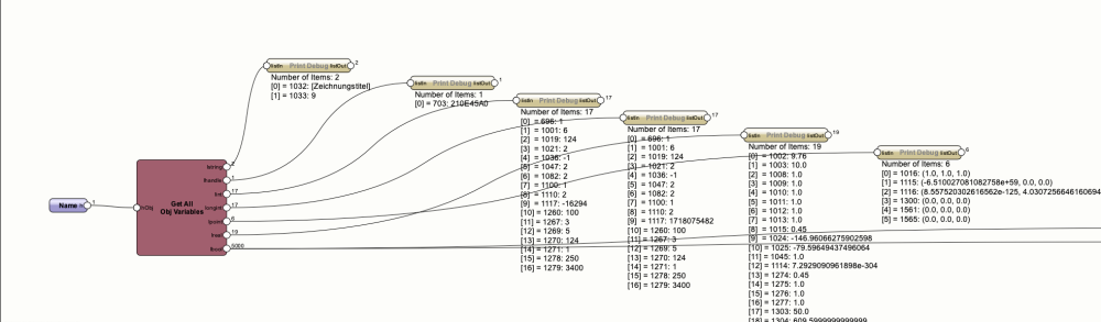
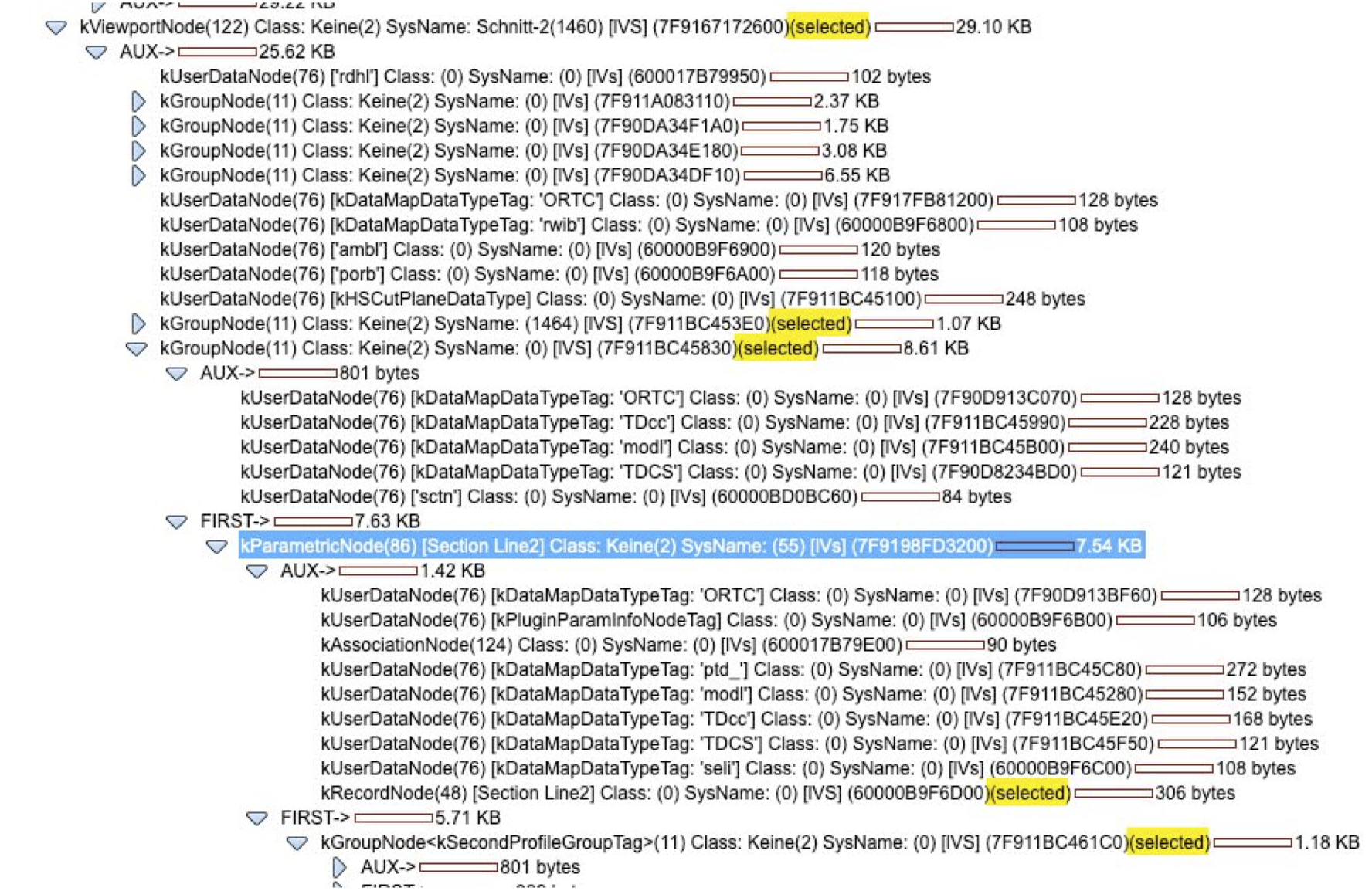
The Marionette Result of scanning the OV of a Viewport from 0 - 5000. I think it would need a function like calling an array but the only array what is callable for object-variables is a point tuple.
-
Thanks for your worthwhile feedbacks. So far my strategy (But I do not know if it will work reliable enough)
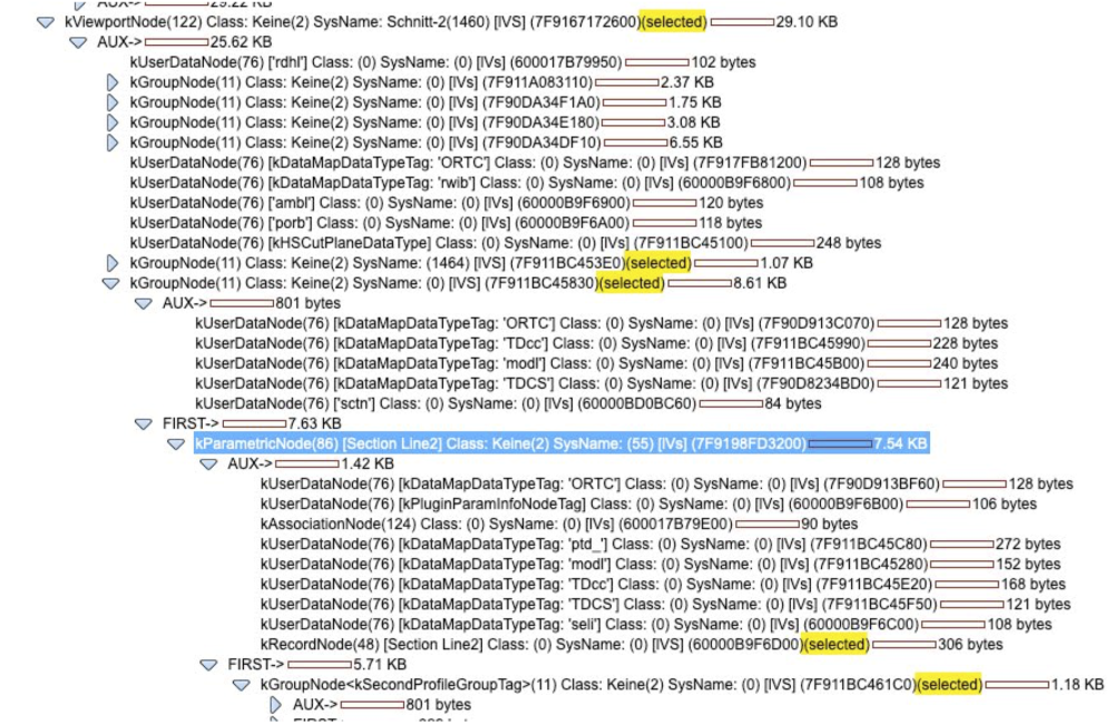
1. Inside the Section there is a Section Line Type 86 that contains the position of the section and a direction matrix
2. There are Informations on the Section VP directly that tells, if section is horizontal or vertical
3. The VP cache Group contains the projected geometry of the elements
In combination of this 3 information it is possible to compare the Design-Layer coords and the section coords.
I build some functions to test what works. So far i see the following stumbling stocks:
- There are differences if the horizontal section was created from clip cube or from sectioning a VP
- VP cache has not the same informations if the objects behind section plane are disabled
- So far my function are not secure to return always the right informations
Prototype Method to get Section Line:
Gets Section Informations
 = vs.FSActLayer()
rname = 'Section Line2'

def create_field_value_dict(obj, rname):
	rhandle = vs.GetObject(rname)
	num_fields = vs.NumFields(vs.GetObject(rname))
	fdict = {'found' : True}
	for i in range(1, num_fields+1):
		fname = vs.GetFldName(rhandle, i)
		value = vs.GetRField(obj, rname, fname)
		fdict[fname] = value

	return fdict

def get_sl_in_vp(vp):
	obj = vs.GetVPGroup(vp, 2)
	#vs.Message(str(obj))
	groups = []
	while obj != vs.Handle(0):
		t = vs.GetTypeN(obj)
		if t == 11:
			groups.append(obj)

		obj = vs.NextObj(obj)

	section_line = vs.Handle(0)

	#vs.Message(str(groups))
	for group in groups:
		obj = vs.FInGroup(group)
		while obj != vs.Handle(0):
			t = vs.GetTypeN(obj)
			n = rname
			if t == 86 and n == 'Section Line2':
				section_line = obj


				break

			obj = vs.NextObj(obj)

	return section_line

section_line = get_sl_in_vp(h)
m = vs.GetEntityMatrix(section_line)
fdict = create_field_value_dict(section_line, rname)
fdict['entity_matrix'] = m
fdict['is_horizontal'] = vs.GetObjectVariableBoolean(h, 1048)

vs.Message(str(fdict))
Prototype Method to get VP cache infos:
This Function puts a 3D Locus on the Design-Layer in Projection to the Objects vertical to Section Plane.h = vs.FSActLayer() rname = 'Section Line2' lh = vs.GetLayerByName('Konstruktionsebene-1') fdict = {} def create_field_value_dict(obj, rname): rhandle = vs.GetObject(rname) num_fields = vs.NumFields(vs.GetObject(rname)) fdict = {'found' : True} for i in range(1, num_fields+1): fname = vs.GetFldName(rhandle, i) value = vs.GetRField(obj, rname, fname) fdict[fname] = value return fdict def get_poly_in_vp(vp): obj = vs.GetVPGroup(vp, 3) groups = [] while obj != vs.Handle(0): t = vs.GetTypeN(obj) if t == 11: groups.append(obj) obj = vs.NextObj(obj) #vs.AlrtDialog(str(groups)) objs = [] for group in groups: obj = vs.FInGroup(group) while obj != vs.Handle(0): t = vs.GetTypeN(obj) #vs.AlrtDialog(str(t)) if t in [5, 21]: if vs.GetFPat(obj) != 0: objs.append(obj) obj = vs.NextObj(obj) return objs objs = get_poly_in_vp(h) fdict['polys'] = objs fdict['is_horizontal'] = vs.GetObjectVariableBoolean(h, 1048) vs.AlrtDialog(str(fdict['is_horizontal'])) #vs.AlrtDialog(str(objs)) def get_center_points(objs): center_points_3D = [] for obj in objs: p = vs.HCenter(obj) if fdict['is_horizontal']: m_pt = p[0], p[1], 0 vs.AlrtDialog(str(m_pt)) else: #vertical section y = z m_pt = p[0], 0, p[1] center_points_3D.append(m_pt) return center_points_3D center_points_3D = get_center_points(objs) for p in center_points_3D: vs.Locus3D(p) locus = vs.LNewObj() #vs.SetParent(obj, lh) vs.SetParent(locus, lh)
And next prototype Method can check if the center point of the section cache-geometry is inside the parent object on the design-layer.
lh = vs.ActLayer()
ln = vs.GetLName(lh)
espsilon = 1

c = "(INOBJECT & NOTINDLVP & NOTINREFDLVP & ((L='l-dummy') & (PON='XG Custom Part')))"
c = c.replace('l-dummy', ln)

custom_parts = []
def add_handle(h):
	custom_parts.append(h)


vs.ForEachObject(add_handle, c)


def is_pt3_in_cube(pt, cube, epsilon):
	x, y, z = pt
	xmin2, xmax2, ymin2, ymax2, zmin2, zmax2 = cube
	# vs.Message(str(cube))
	overlapx = overlapy = overlapz = False

	if xmin2 - epsilon < x < xmax2 + epsilon:
		overlapx = True

	if ymin2 - epsilon < y < ymax2 + epsilon:
		overlapy = True

	if zmin2 - epsilon < z < zmax2 + epsilon:
		overlapz = True

	return min(overlapx, overlapy, overlapz)


def bbox3D(p, zValue, height, width, depth):

	centerPt = (p[0], p[1], zValue)
	botZ = zValue - depth / 2
	topZ = zValue + depth / 2

	w2 = width / 2
	h2 = height / 2
	bbox_bl = p[0] - w2, p[1] - h2
	bbox_tr = p[0] + w2, p[1] + h2
	bbox_tl = p[0] - w2, p[1] + h2
	bbox_br = p[0] + w2, p[1] - h2

	xmin = bbox_tl[0]
	xmax = bbox_br[0]
	ymin = bbox_br[1]
	ymax = bbox_tl[1]
	zmin = botZ
	zmax = topZ

	return [xmin, xmax, ymin, ymax, zmin, zmax], ((xmin, ymin, zmin), (xmin, ymax, zmin), (xmax, ymax, zmin), (xmax, ymin, zmin), (xmin, ymin, zmax), (xmin, ymax, zmax), (xmax, ymax, zmax), (xmax, ymin, zmax))

#h = vs.FSActLayer()
h = custom_parts[0]

parent = vs.GetParent(vs.GetParent(h))

BOOLEAN, offset, rotationXAngle, rotationYAngle, rotationZAngle = vs.GetEntityMatrix(parent)

(p, zValue) = vs.Get3DCntr(h)
(height, width, depth) = vs.Get3DInfo(h)

cube, pts = bbox3D(p, zValue, height, width, depth)
is_in_cube = is_pt3_in_cube(pt, cube)

for pt in pts:
	x, y, z = pt
	x = x + offset[0]
	y = y + offset[1]
	z = z + offset[2]
	pt = x,y,z
	vs.Locus3D(pt)
Additional it would help to check classes and attributes to be sure not targeting an invisible object etc.
With this 3d Methods it is possible to manually make a relation between a coord point inside the section annotations and the object on the design-layer.
The shakiness of this strategy here is, that the Method of traversing the VP to collect Section-Line and Section Geometry is maybe not reliable enough or can wreck after an VW Update.
Further it can be tricky to get positions of rotated and nested object rotations. That would be the the hardest part. Even the Data-Tag hat some (fixed) issues to find the Objects in every situation so I do expect that would be really expensive to solve that.
Also I saw, that I corrupted some VP after working on them with this scripts. But I think this was because of creating Test-Marker-Objects inside the VP. At the end, this would be a "read-only" access to the VP which should not corrupt anything -SHOULD.
I will pause working on that specific feature ☺️
-
Hi
Does anybody know, how to get a handle related to the geometry of the vp cache "vs.GetVPGroup(h, 3) or the VP coordinates to the Object on the Design Layer?
Target would be tagging or annotate Elements in a Section viewport by script. Somehow it would work because the data-tag can also can access to this elements.
I can imagine that it is necessary to evaluate the original object of a location from the vp coordinates and the section plane. Or is there an other solution for that?
DomC
-
On 3/3/2023 at 1:27 AM, cavan.smith said:
small, we need it to be 1000 instead of 10.
Hi
Hm, I was quite sure "SetTexBitFeatureSize" changed once the texture size. However I would confirm, the size is always 10mm, 1cm or 0.01m.So far what seems to change the size (but not as we needed)
1. Changing the Document units to the imperial unit-system inch. Texture size is now 1 inch instead of 10mm but somehow other units do not change the size.
2. If I change the linevs.SetTexBFeatureEnd(hTextureBitMap, int(resolutionx*100), 0)
The Size is 100 times bigger but this value is not update till i go into the dialog box of the texture.
Also Tried:
Layer Scale, Different units, scaling the image, scaling the paint. Reload Document.
So it seems, we have not a solution for the default texture size yet.-
1
-
-
OK I can reproduce two issues. Wich looks not like a messed up script it looks like an issue with the style duplication and replacement on a new document.
1. Importing Style to new Document and edit the object or insert a second one2. import and Edit the style and import and replace new from source
The Styles Marionette PIOs are a new System since VW 2023. Before that we got the workaround with Script-Symbols inside of the PIOs which worked quite good at the end. It is very hard do foresee all workflow and issues in development and so I think the styles need a little time to loose the growing pains.
I will bug-submit those two issues.
-
2
-
-
The File was saved with SP2, maybe first try Updating on SP3.
Also I can't see the issue in SP2 and SP3. But I saw this kind of errors in early SPS of VW 2023. I reported a lot of them they are all fixed. Please try to exactly find out, what steps are necessary to got the broken result.
-
1
-
-
I think I found it
vs.GetPolylineArcMaxRadius(hPoly, vertexNum)
Just to close question .Correction in the loop by return 0 if Vertex Type is not Radius or Arc. Also harmonized units, this function returns mm (which is in my opinion very progressive if everything would returns mm and not document units > just a thought but how many code would fail after such an update :-). So good just new things returns mm. However here my little fiddleobj = vs.FSActLayer() num = vs.GetVertNum(obj) units = vs.GetPrefReal(150) output = [] for i in range(1, num + 1 ): p, vertexType, arcRadius = vs.GetPolylineVertex(obj, i) if vertexType in [3,4]: arcRadius = vs.GetPolylineArcMaxRadius(obj, i) / units else: arcRadius = 0 res = p, vertexType, arcRadius output.append(res) vs.CreateText('\r'.join(map(str, output)))
-
Hi
Did not find some hints in the forum, so a deside to make a new post. I think I am doing something the wrong way. But What I want to do is, to grab directly data of a polyline with arcs and radius without converting them or decomposing them. So the GetPolylineVertex command looks like the right workflow for this. But what I can see (depended how the polyline is created or which tools are used to modify it) it returns the radius not directly on the returned point index.
The only pattern I can see is, that the last radius which was returned before the vertex point is the right radius. I can imagine, that this workes as designed to bequest the value to the next value which is 0. But somehow not logical is, that other points which are type 0 (edge) contains the radius value. Someone see behind the scene here?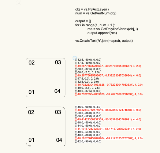
-
Maybe you also could recycle this marionette script. It will create a record from an external list of record fields.
creating records from txt or xls. Also in the Marionette you could find the script commands you need for creating fields and record formats.-
2
-
-
Hi
Maybe just the Variable Name "Zubehör" is the issue or return list. Try Changing the names of those two variable Names. list() is a python function and should not be used as a variable Name. Also special Character in function or variable names could maybe creates an issue somewhere.
The rest I can't say much. You could test by renaming or deleting objects (take care about crashes) to see, where your handle is pointing to.
Also caution with the nodes. If it returns None/Null maybe the print node attach the type to the prior object or something like this. I would first take the code out of the marionette nodes to search the bug.
-
Hi
I am pretty sure, it should be possible by worksheet formula without script, is somebody long enough work on that Formula. I first attempt could be a hard-coded formula (one Formula for one parameter in one PIO)
=TEILSTRING(TEILSTRING('MarionetteObject2D'.'NodeDef_OIPControls', ',', 6), ':', 2)
While "Teilstring" is "SubString" and in Germany ';' must be used as delimiters instead of commas i guess. But it returns the Width of the Marionette Object. Also the reversed procedure should by possible by concat worksheet formulas. Never thought about this. 2 is the second parameter and 6 is the value.
Edit: Hm reversed procedure could be tricky by writing at all data from a formula on the object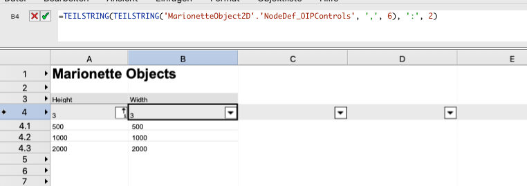
-
Great Guys
How cool is That! I will for sure use it soon to lay floor-panels soon in my basement hobby-room. Don't forget to share in the gallery.-
 1
1
-
-
This kind of behavior is quite common. Often we need a "ResetObject" or a "ResetBBox" after some commands. I would not say this is a Bug or an error because it can be smart to not reset and recalculate everything in every single Node/Step of a script to keep it fast.
The "GroupNode" resets the BBox. Also the Geometry-Grouping of Marionette Network resets the BBox of the PolyGroup by accident.
You can reproduce the same behavior with a Script.
h = vs.FSActLayer()

num, polyGroup = vs.TrueTypeToPoly(h)
bbox = vs.GetBBox(polyGroup)
vs.AlrtDialog(str(bbox))
vs.ResetBBox(polyGroup)
bbox = vs.GetBBox(polyGroup)
vs.AlrtDialog(str(bbox))
The vs.TrueTypeToPoly() returns a group with zero size Bounding Box. We have to first reset the bbox to get the bbox size correctly.
Or in the Script: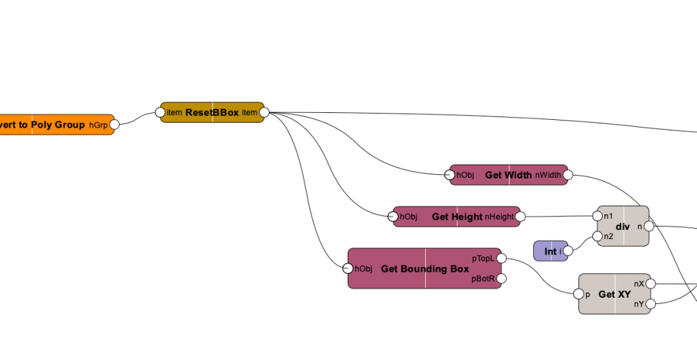
Unfortunately, resetBBox (also ResetObject which is also a common needed Node) are not part of the standard Node-Content.
-
3
-
-
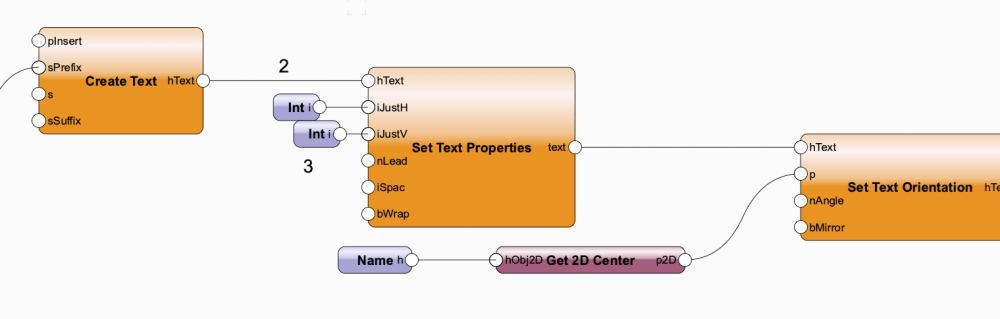
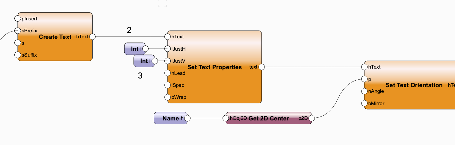
Agree with Antonio. Alternatively set Text Properties to middle and then set Orientation to your point.
-
2
-
-
Hi
I wrote "low effort" so I triggered myself to try it. Here your example. I count here every 20th pixel. this is the input "Rasterabstand".
What is not solved is, that the blue pixels as example not have exactly the same value. Also it counts also the white pixels. But it is a base, just to answer the initial question.
Oh yes, Marionette can.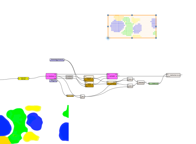
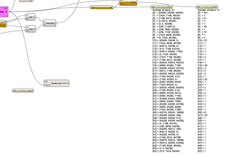
The Picture have 51 different colors. Here the counts:
-
2
-
-
You can count pixels of an image by using the pillow library for python. You could install that library in 2023 with the new installer from Marionette. Some of the earlier installation nodes (from me and others) fails because of different reasons (wrong wheele Files, ssl incompatibilities etc.) But once your pillow library was working you can do that. You cant count the pixels and colors. Maybe you have to "round" color because not every green pixels have the same green etc.
but it is possible with low or maximum medium effort. Some existing examples:
1. How to digitizing an Image: It counts the pixels and the the rgb values.
2. An Example how to seperate Clusters of Points.
3. An Example how to create a Hull around a "cloud" of Points. If you have generated points out of your image, you could make a shape out of this points with that.
A note about Example #2 and #3. This is perfectly already solved by using an external Library like shapely etc. They can generate convex and concave shapes out of points. Also There are many other Libraries that can vectorize your images pretty good.
-
2
-


Question on DomC's "Extrude along Path with Ref point" Network
in Marionette
Posted
Hi
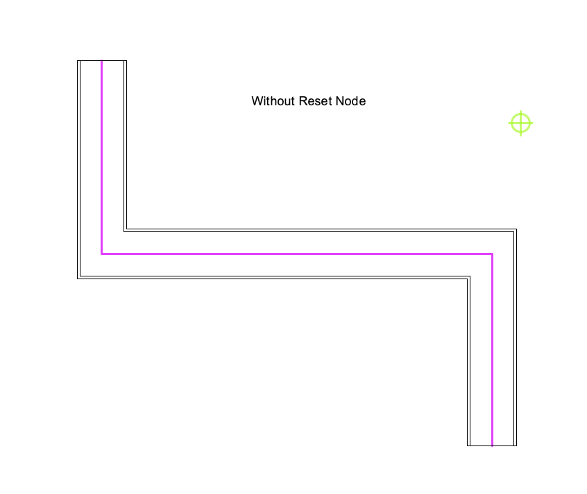
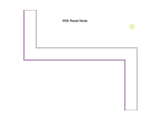
After specific Manipulation there is a need of ResetObject. Some commands included the proper Reset of the Result some not. In my Script you can see, that if you remove the reset of the parent object, the visible geometry is different from what you get if you edit the path extrude and exit it (same effect as resetting). If for your example it is not needed (because you do other actions with the result which may reset the objects itself) you can delete it. Beside that, it would not have a big speed impact because in a script every reset is added together if you reset 10 times it will reset just once anyway.
"Punktkörper" is called "Mesh".
Not sure I understand this question. You mean the result of your solid boolean operation is a mesh? Normally this is not the case at all. The Result of using solid boolean node should be a generic solid not a mesh. Even if you use a mesh in a solid operation the result is normally converted to a solid not a mesh.