


DomC
-
Posts
605 -
Joined
-
Last visited
Content Type
Profiles
Forums
Events
Articles
Marionette
Store
File Comments posted by DomC
-
-
 20 hours ago, MJU said:
Hi DomC,
first of all thank you this is great work and so useful. From your point of view would it be possible to modify the script in order to create rectangles with Data Tags?
I'm trying to follow a more 2D oriented hands on workflow because with lots of changes and adjustments spaces get laggy and messy very easily. But I still don't want to miss out on your great script and the ability to analyze the data.
Would be nice to have a qualified opinion on this approach.
Thank you. I wonder, why the most usefull things always have the lowest rating here 🙂
Using Rectangles instead of Space PIOs could make definitely sence.
To have rectangles instead of Spaces you could modify the script as following:
1. Create a Symbol with a Rectangle inside and link it to your record format. So you save that part of setting record to objects and tagging objects by script.You can Tag the Rectangles at the end with the "multi-Tag-Methode"
2. Modify the brown Wrapper like this. It would result in a much more simple script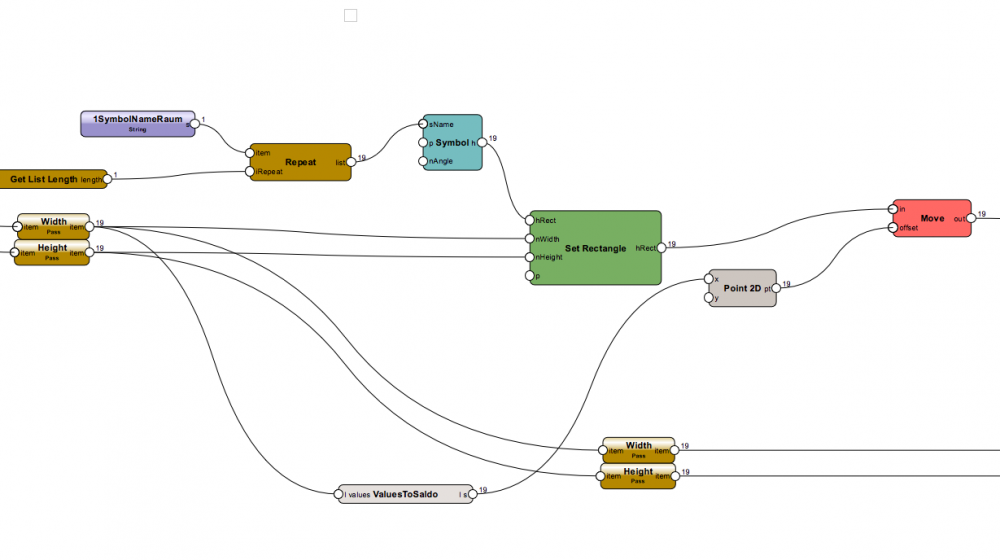
3. Then you have to edit the "Set Record Field" part of the script with your own record name instead of "Space".
Other Options also possible but I think this is the most easy workflow.-
 1
1
-
-
Hi
Green is a Page Bases Symbol. Red is a Parametric Intelligente Object (a space or a DataTag as example)
The Other Point (switching between Styles) I can't reproduce. The Data are transported (if unstyled Field) from one Space to the other and Back.
-
 On 12/7/2020 at 10:26 AM, t.aichele@freudig.com said:
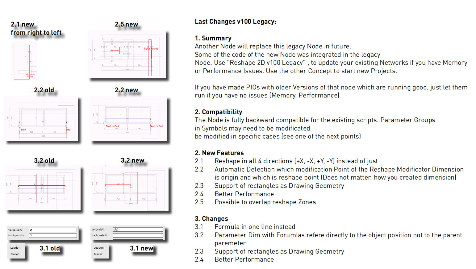
Hi Dom, thanks for the good puppet! I am currently using this on doors. Can it be that this puppet only allows a shift from left to right and from bottom to top? Furthermore, I cannot calculate correctly with the script, which math functions or symbols can I use for them?
The actual Version, is able to shift from right to left, top to buttom also. +-*/ and all parameter input names should work.
-
Hi
You could directly connect the xlsx reader instead of csv reader, this works perfectly.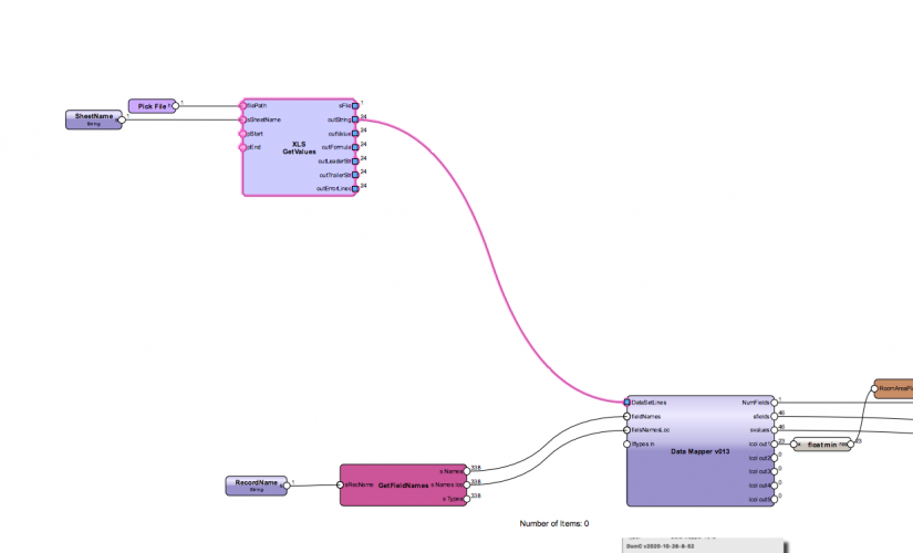
I would first try this one because if you have an excel File this would be the direct way (If it works, because text encoding is a real pain). By the way your worksheet for me looks like an encoding issue too 🙂 Maybe not just islandic?
Also the First version v2018, uses a Vectorworks Worksheet for input. This still works and you could just connect the worksheet reader instead xlsx or csv reader.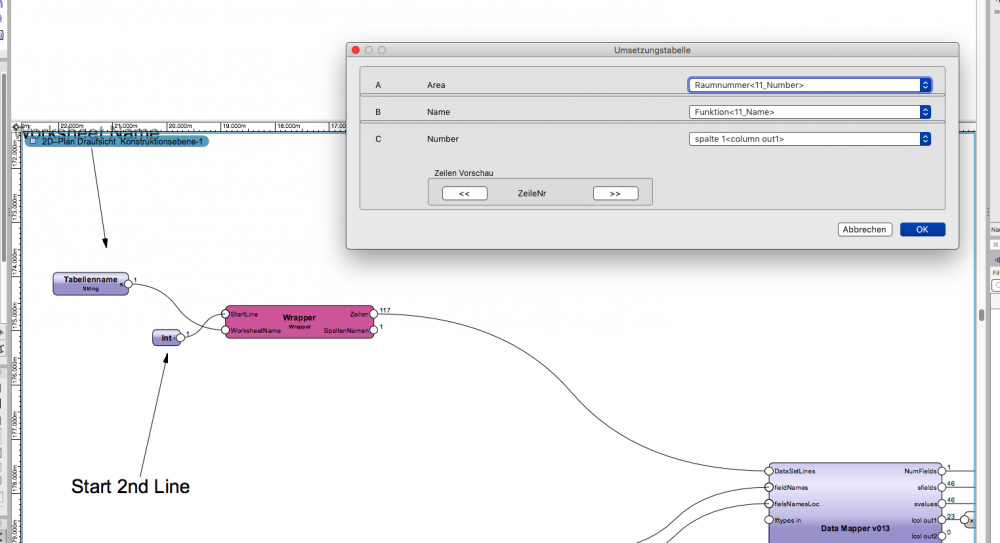
-
1
-
-
On 3/18/2020 at 1:48 PM, sp@schankula.com said:
Hi Dom,
great tool, i'm very glad i found it!
Is it possible to change the output "m2" to "qm"?
New Version is available you can directly enter the unit for the aria as a suffix
-
Hello
Nice Antonio, great Page 🙂
Alternatively in the new Version 1.0.3. there is a Node "Get Field Names", which can show you the localized and universal names of record fields.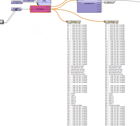
-
12 hours ago, t.aichele@freudig.com said:
Can it be that this puppet only allows a shift from left to right and from bottom to top? Furthermore, I cannot calculate correctly with the script, which math functions or symbols can I use for them?
1. Shift the Geometry by half of the Parameter, so the object would keep his middle
2. For Calculation Extract the Input Parameter with Get XY. Also to could feed the input Parameter with Point 2D If you don't want to show Parameter Name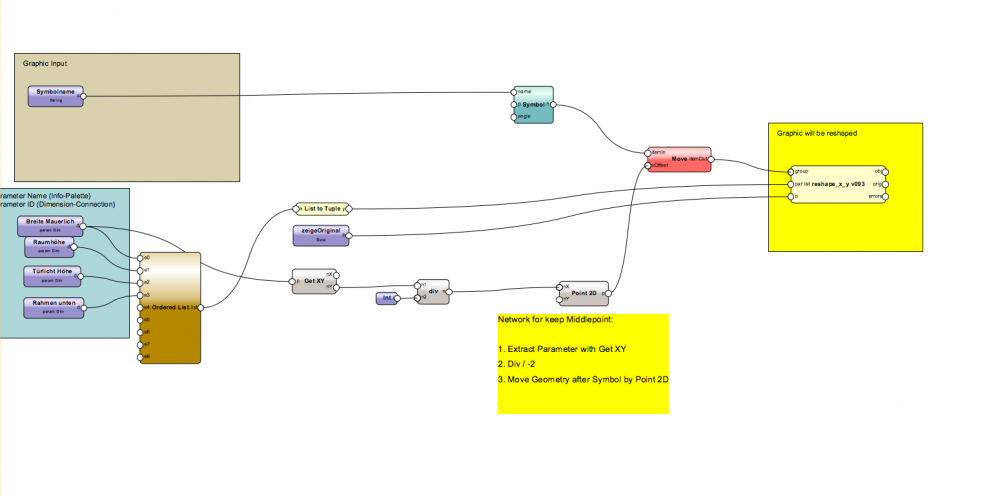
-
On 10/15/2020 at 9:55 AM, elepp said:
Hi DomC,
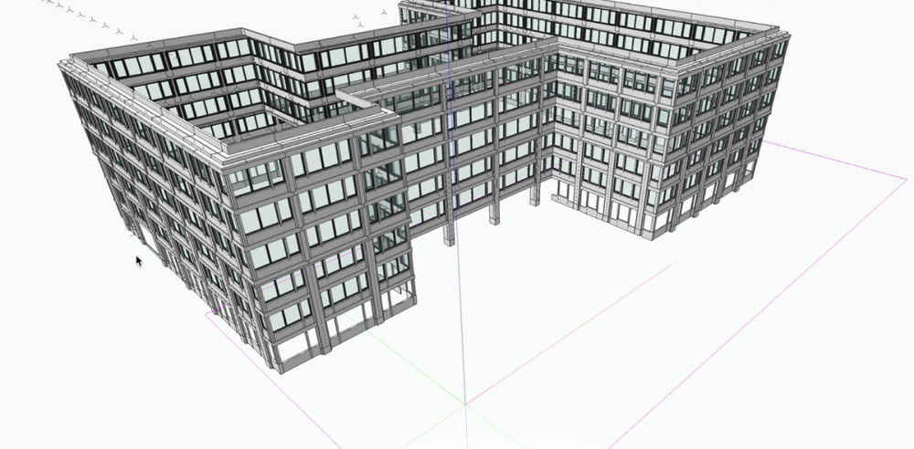
great node. I even managed to attach an ifc-record to the object. We encounter though one problem. We tried to use a symbol instead of group as control geometry. It worked for rescaling it but interestingly enough it looses its graphic attributes. In the screenshots you can see the marionette object in white and inside the control geometry you can see the original colors. Any idea why that is or how to solve it?
Thanks in advance!
Hi @elepp
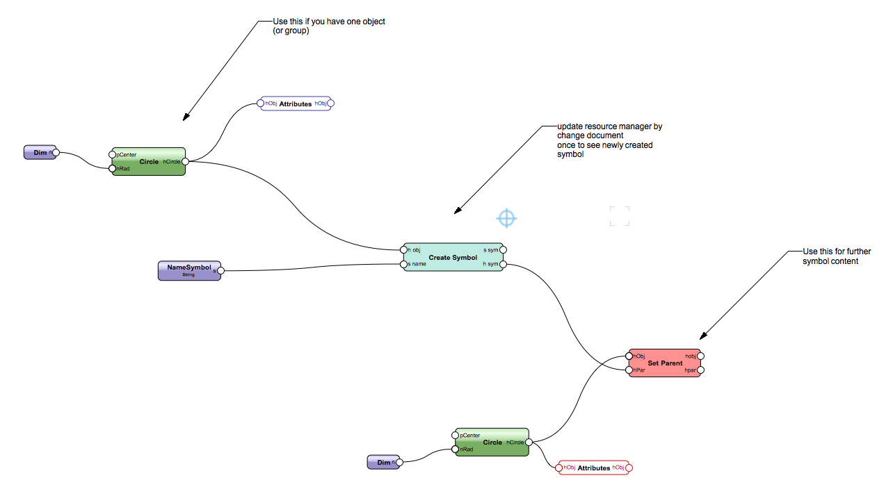
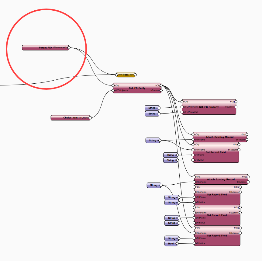
Hi If you put the complete Symbol into the Node, it will "flatten" the geometry inside of it.
You have to Make a blue Symbol. Then attach the IFC Date to the PIO container with the Parent PIO Handle. Like this: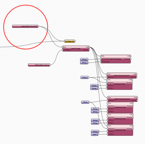
If you just want to have the Object is an IFC Object without any Detailed Informations, you could map IFC Informations with the Datamanager class Object.
-
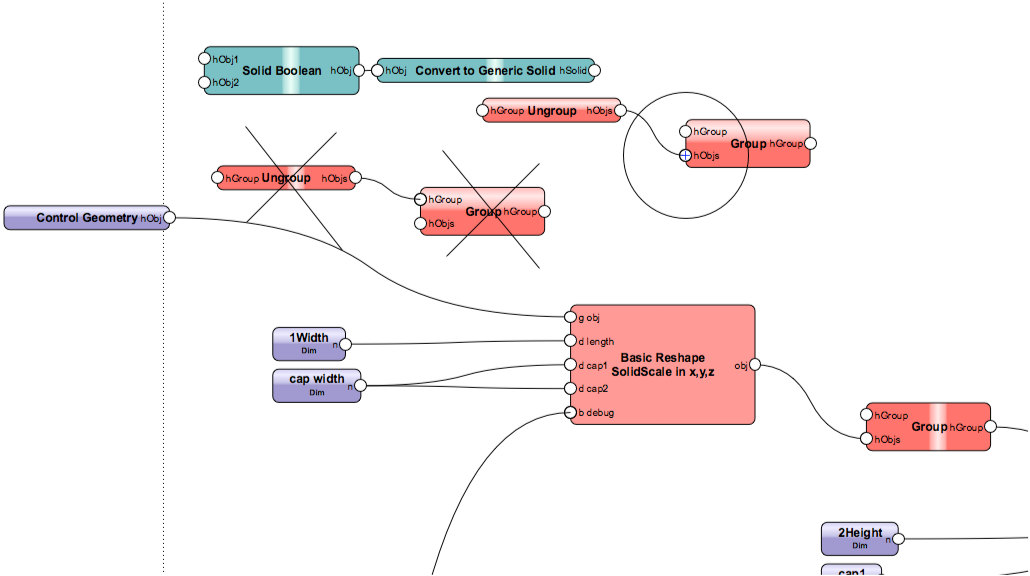
The input of the node has to be a group. You don't need to ungroup before.
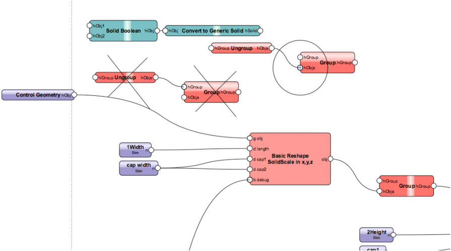
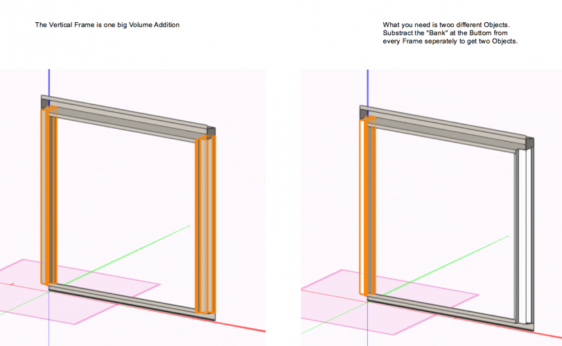
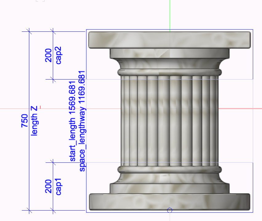
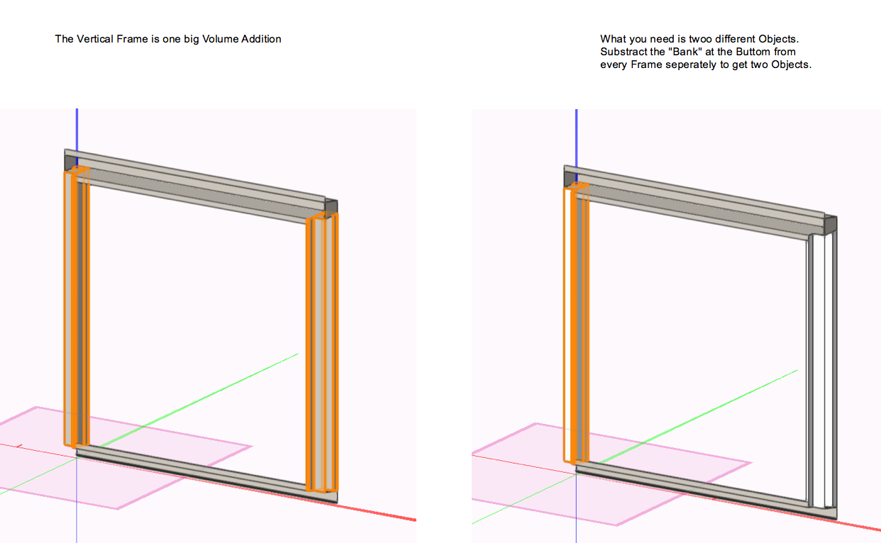
The Issue seems not bei have a solid Operation inside of the Control geometry. Seems the issue is, that the Node does not handle the "One Big Volume" of the vertical Frames by reshaping the z- direction. I think it is a "Bug" in the Node or a "Limitation". I would suggest the "Workaround" to have two seperate vertical Frames (extrudes, Volume Substraction etc. does not matter). I am not sure where the error is. I am sure, that I have examples with Glass inside and also this is "One Big Volume" so it should work but not in this example. Also there seems to be different Versions around of the Node. I will look into the node and maybe provide a new Version maybe in some month, when I have a little more time.
-
1
-
-
Hi
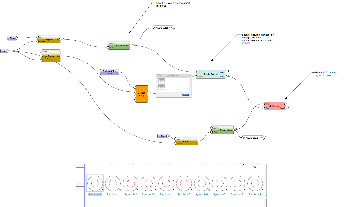
First lets talk about what is an Object List?A List in Python ist like ['Symbol1', 'Symbol2', 'Symbol3'] Used by the any input it will produce one line for every symbol name. This ist the input, the symbol node wants
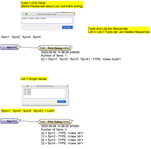
But yes, we can input a List of objects. Example:
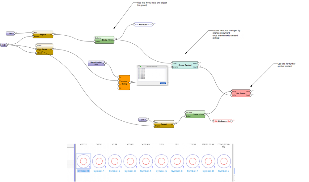
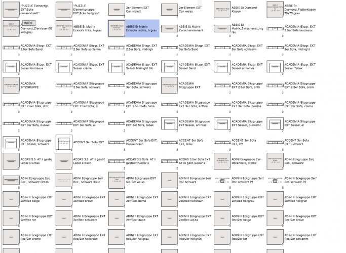
This node was made to produce over 15'000 furnitures at once from an external list of objects.
-
I am back from vacation so sorry for late reply.
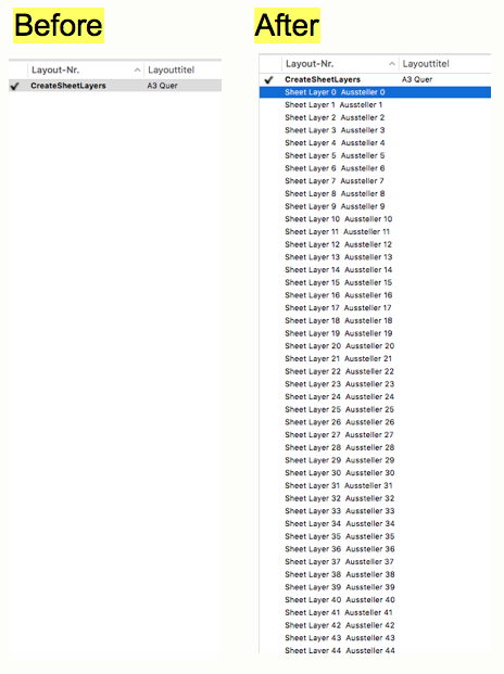
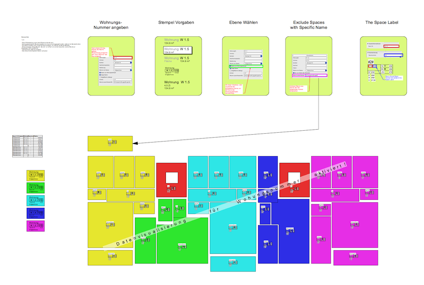
Basically this Example do the following:
1. Collect Objects in the drawing with the criteria node
2. Read some informations of the objects and put them together with a viewport on different sheet layers.
3. additionally it creates a title block with some informations about the object
You can do this for all objects independent if they have a record or not.
It is just an example. Because it is a Marionette feature you could enhance or change, what the script should do (Maybe group all spaces from one layer on the same sheet layer, maybe collect additionally informations from objects which are in the space or on bound of the space, etc. etc.)
To your question:
All spaces are already linked to a record format (Datenbank).
Specific the Example with the spaces, uses the room Number for naming the sheet layers. Also it reads data for write them to the title block.
If your spaces have not the informations as the script excepts (No Room Number, No Name etc.) it maybe will not run. So if your spaces and informations are not the same type as in this example the script has to be fit to your space informations. You could share some of your spaces, that would help understanding if an issue appears
-
1
-
-
Hi Pier
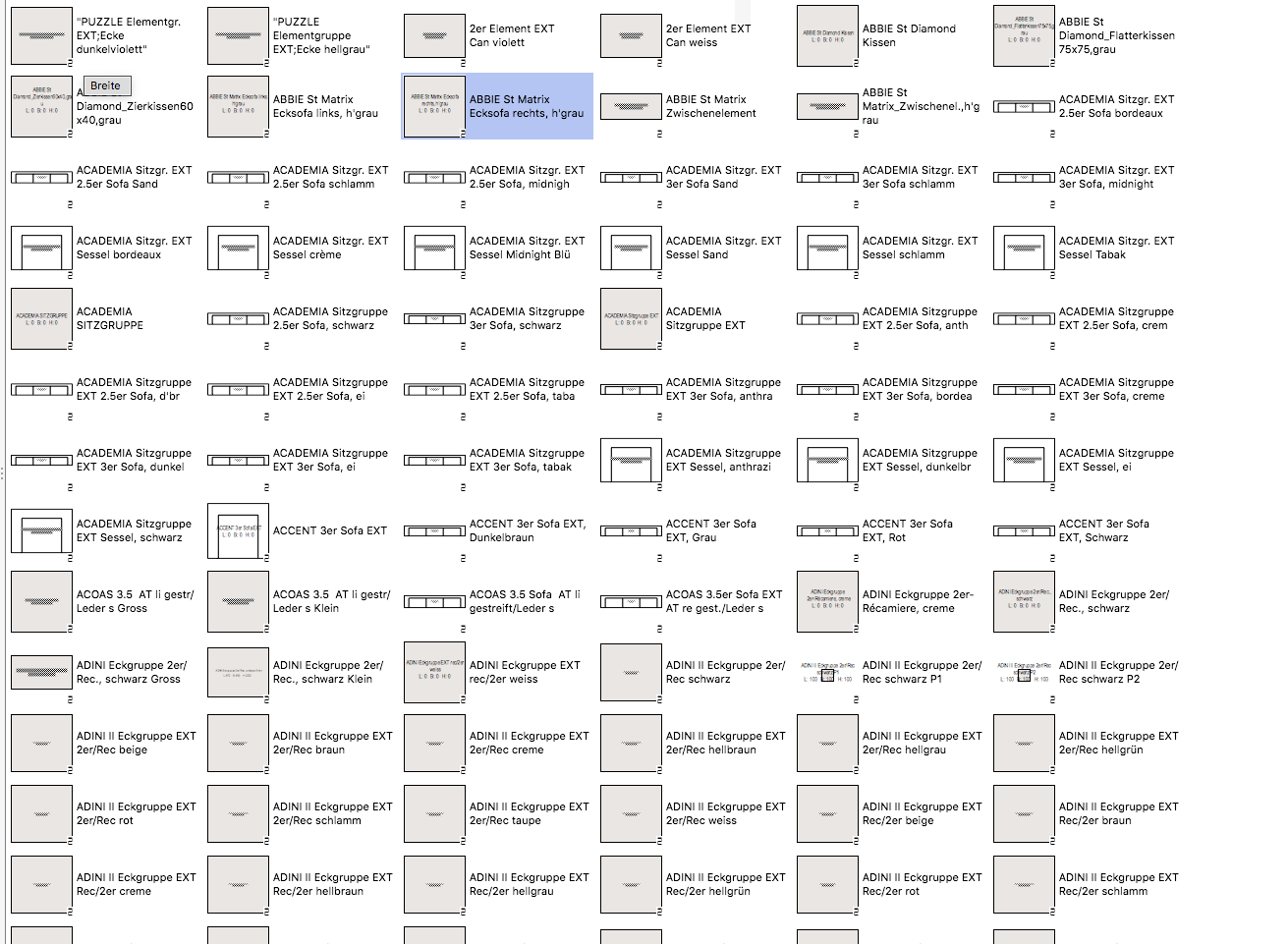
The Node used the outdated vs.GetType() command which do not work in 2019 and also produced wrong handles in 2018. New Versions uploaded. I fixed this long time ago but forgot to update this here in the forum. Beside that, this node is in use in several real live projects (as Example the fassade (Window Elements with additional frame and all ifc informations) below is made with this)
-
@Boh
Uploaded a fixed v2018 example similar as the 2019 Version. It does not use the input wrapper. Instead of that it uses a red symbol from a space object.
-
Same Issue like in many other Scripts which uses the SetRecordField Node. I fixes that (Replaced SetRecordField with the ne 2019 Node)
-
1
-
-
Hi Onyx
It is everything possible, what we can also solve with Vectorworks functions. The Question here is, how to make views from a single furniture and hide all others. The standard workflow I recommend here is, to draw every single position on different layers. So we are able to work on every furniture/position undisturbed from the rest of the drawing. Also we can rotate them in a front view to work on it. Then make Design layer viewports from this furniture and assemble it on a master view. That's the way I would structure it.
From your structure it maybe could be solved as following:
1. Different classes for every furniture. Maybe automated class-naming with the position descreption or furniture name and then Automated layout with class visibility.
Or
2. Sections around the furniture. But I am missing my KnowHow how to make sections with a script and also the issue is, that the sections will cut the furniture which is beside the required furniture.
So #1 or a better Idea could be a base for a Marionette automation.
-
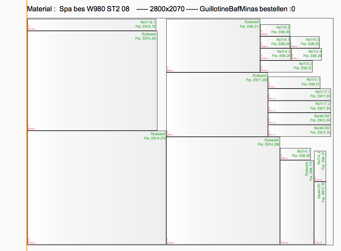
Hallo
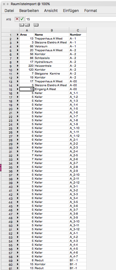
Ich kann mir das gerne anschauen. Es gibt zwei Tabellen-Inputs. Einerseits die Teileliste, andererseits eine Plattenliste um für verschiedene Materialien, verschiedene Plattengrössen zu definieren und um zu sehen, welche Platten bestellt werden müssen. Wobei man auch bei der Lager-Liste Stk 1 verwenden darf, wenn man das nicht braucht.
Also Board-List ist der Platten-Lagerbestand und Stückliste-Küche ist die Stückliste. Es könnte dann Fehler geben, wenn die Spaltenreihenfolge nicht stimmt, die Zahlen mit Komma getrennt sind (7,1 statt 7.0). Poste doch mal Deine Beispieldatei und Beispieltabelle.
-
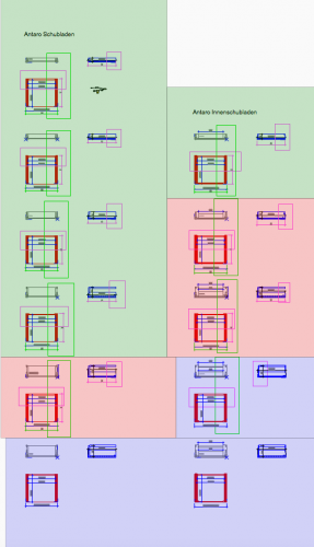
Another example usecase of parametriced drawers.
-
3 hours ago, Pat Stanford said:
I think the 11_Area actually returns the value in the current document unit area settings.
Hi Pat
Thanks for reaction. You are right and I already switched to 11_Area in the 2019 File.
-
@Luise
It hard to intercept every bug in other components but I think this Update will fix it:
1. Uses 11_Area which seems to be m2 instead of cm2
2. separate numbers from unit and can handle , as dezimal delimiter.
3. Returns 0 for Bottom elevation if elevation is negative (can't fix this, maybe I could by getting the IFC elevation height, but I don't want to)
You can try the attached Update File it will work without error Message
-
Are you testing in 2019?
In 2019 space delivers cm2 for area and negative elevations will result in empty output. That will result in issues because the script is not made to deal with empty input. I will look what.
Also the "Get Record Field" Node from 2018 will be broken in 2019.
-
Hi @Luise
An Update is available. Now it eats comma separated numbers together with units.
-
1
-
-
Hi
There is an update. The "VP Layer Visibility" has no bug. It just set the same visibility in all created vp. So not very usefull for creating more than one viewport with different visibilities. However I made this node new. It works now with different input sequences. So every created vp can have different visibilities.
Quotehttps://forum.vectorworks.net/index.php?/files/file/182-automated-layout/
Updated Nodes:
Set VP Layer Visibility
Set VP Class Visibility
New Node:
Get Saved View Visibility (optimal for view saved classes for classes). Suspicion to be slow ... with over thousands of spaces
This Project seems to have a big demand. So I plan to make other examples in Future, if nothing more important comes up:
1. Putting several spaces on one layout. Lets say all spaces of one layer maybe. By the way, 1500 Sheet layers are not an issue at all with 2019 and the new layer
2. Naming Viewports by a system. Let's say Layer+RoomNumber+RoomName
3. Update function for existing layouts. Just new rooms will be layouted, not all spaces again. So it will by fast with 4000 spaces
4. Try with detail viewports maybe (not sure if it's possible maybe same issue like sections)
5. Sections could be interesting (whereby i tried and already failed ... maybe with 2019, let's see)
6. Meaningful Ideas and "customized" solutions also.
Post your successes !
-
1
-
-
Hi Matt
Hm ... it's seems to be a bug in the "VP Layer Visibility". I will look into this to provide a fix.
-
the first two handles are different from the others.
Follow the handles from right to left in the script. Then you will see, that they are strings before they got handles. They also will be the same string. That's how I search an error. Like the TV, if cable connection is broken. Follow the cable back and you will find the faulty connection.
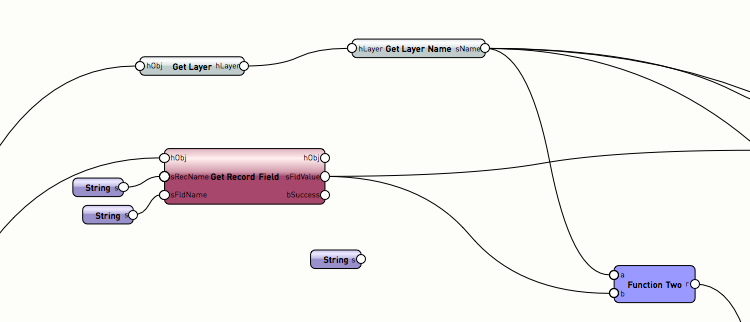
The name is built from the Room Number "11_Number". Which maybe is empty in your file and the Layer name of the space. If this is being the case all spaces from one layer will putted on the same layout on the same place. To fix that:
1. Take another (unique) data from the space. Or create room numbers
2. Feed the Sheet Layer name producer with a series of numbers.
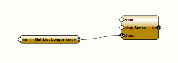
3. Make the Position of the Viewports a Serie of coord Points and the will lay side by side.


SpacesfromList.vwx
in Marionette - Networks
Posted
Ahm ... good found
I provided a new Version (1.0.4) which handles editing of the space boundary different and this seems to work (hope for many years :-)