

DomC
-
Posts
605 -
Joined
-
Last visited
Content Type
Profiles
Forums
Events
Articles
Marionette
Store
Everything posted by DomC
-

Module 'certifi' not found on VW2023 / Windows 10 Pro OS
DomC replied to Paolo's topic in Python Scripting
Maybe you make something like this and skip the certificate update? Maybe it is not necessery to import certifi on windows and the request will work without certifi? And then skip the ssl context part.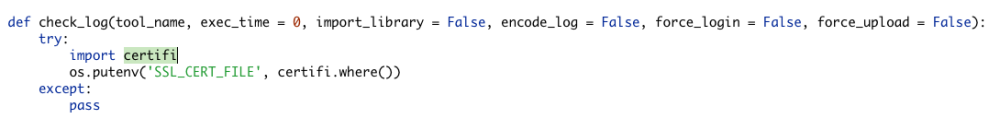
-
Marionette is a Programming-Tool. In such tools wer are in a place to have the force to produce wonderful artwork or unwanted behaviors (crashes?) and comparative we are mostly alone with our artworks. And thanksfully there are forums like this other people can help for bringing those projects to success. I took a look a the Marionette Control-Point and agree, there is some space for improvement: 1. Fixing Axis I think @Gregi wantet to fix one axis. This is not possible because the position of the control-point comes from the Mouse not from a value inside the script. This value is just a default value. To change the control point by script itself is theoretically possible to manipulate the Record of the Marionette Node where the position of the point is stored but it would be very hard (Because also the position of the PIO is involved). So this is not a bug it works the way the feature is designed. 2. Moving 3D Point in Standard View. If I am in a standard view (front right etc.). Lets say from right and I move the point in z-Direction, the x value from the point snaps on the working plane and the x-value gets 0. Which can maybe produces issues in the script inside the PlugIn. So working plane should be used or unwanted values have to be intercepted inside the script (which is always the most costly part). So if the script crash because the width of the pio change to 0 it is not a bug in the code of the 3D modification point. It is just an unhandled error. Error can be handled on different places. In shoft: OK, I can see, that the reshape behaviour of this modi-point can be improved and i will report this as an enhancement Request. 3. Position of the 3D Point outside of PIO geometry. If the Modification Point is the most outside object in a PlugIn. And not geometry is there, the position of the Point somehow is calculated wrong relatively to the object. So in our test with Extrudes etc. it always works as expected. But If the extrude is smaller than the bbox of the modipoint and the 0-point it somehow Fails. I think, this is definitely a bug. I will report. 4. Position of the 3D Point with layer elevation I think this is already known but I try to give it an impact. Generally, there are not much additional layers of error-handling between marionette and the Script Engine. I think the more "idiot-proof" something is made the weaker it is. Not 100% the truth (It could be possible to have both). But this is the way I am still pleased even if my script crashes 😁
-
This may also help
-
OK, the part of the code which I will not paste is the part how you update your certificates by the script on mac computers to make python accept them to communicate over TLS (SSL) (https instead of http). caution should be exercised.
-
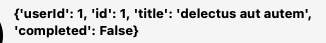
The forum allows me not to paste some code ... I think maybe for security reasons. Or your testing api request: import urllib.request import json api_url = "https://jsonplaceholder.typicode.com/todos/1" result_string = '' with urllib.request.urlopen(api_url) as f: result = json.loads(f.read().decode('utf-8')) vs.AlrtDialog(str(result)) An other real example with a http request url, if you can't get https to work import urllib.request import json import math #dezimalgrad in minuten und Sekunden umwandeln (copy paste aus dem Netz) def deg_to_dms(deg, type='lat'): deg = float(deg) decimals, number = math.modf(deg) d = int(number) m = int(decimals * 60) s = (deg - d - m / 60) * 3600.00 compass = { 'lat': ('N','S'), 'lon': ('E','W') } compass_str = compass[type][0 if d >= 0 else 1] return '{}º{}\'{:.2f}"{}'.format(abs(d), abs(m), abs(s), compass_str) h = vs.FSActLayer() x = 2600000 y = 1200000 z = 500 #Nimmt Position von aktiviertem Hilspunkt, Objekt oder Symbol sonst Bern Sternwarte als Vorgabewert if h != vs.Handle(0): x,y,z = vs.GetLocus3D(h) #vs.AlrtDialog(str(vs.GeogCoordToVWN(x, y))) vs.AlrtDialog(str(vs.VWCoordToGeog(x, y))) xPt, yPt, zPt = vs.PtDialog3D('LV95 Koordikante zu WGS84', x, y, z) #Abfragestring auf dem Geportal direkt im Internet url = "http://geodesy.geo.admin.ch/reframe/lv95towgs84?easting="+str(xPt)+"&northing="+str(yPt)+"&altitude="+str(zPt)+"&format=json" result_string = '' with urllib.request.urlopen(url) as f: result = json.loads(f.read().decode('utf-8')) #Antwort vom Geoportal interpretieren und umwandeln in json result_string = str(result['easting']) + '\r' + str(result['northing']) + '\r' + str(result['altitude'])+'\r\r'\ 'Grad: ' result_string += '\r' result_string += 'Grad Minuten Sekunden: \r' + deg_to_dms(result['easting'], 'lat') +' ' + deg_to_dms(result['easting'], 'lon') vs.AlrtDialog(str(result_string))
-
Maybe not necessarely. urllib is a standard library and also should do the job. Give a usable feedback or your request:
-
Marionette Node to insert symbols in rows
DomC replied to DomC's topic in Resource Share - Marionette
Oh, this is an old code and not very nice one. Without testing: 1. The vs.GetType should replaced by: vs.GetTypeN(res) 2. The node returns not the Symbol Name. That means the node itself insert the Symbol. In fact it looks, like the output just returns the last inserted symbol. Which means the node should insert the symbols in the number of rows and should do the job but not returning the resulting symbol handles. With that node, you can't use the output useful disconnect symbol node and print debug node. -
Agree with Letti I would vote for the smart solution using the function node without wrapping.
-
 Edit: Added a New Version 1.0.2. where the script tries to convert non-valid cell numbers to numbers. The script tries to convert every cell so I hope this has no other negative effect. However the the existing Example is Version 2023 and works also on my Windows System with Swiss-German and German Keyboard Layout (Switzerland uses Decimal seperator ".", Germany uses ",").
 -
Seems like this is the case here. On windows OS, some Input Fields convert to comma decimal separator. Der Input darf keine Kommas als Dezimaltrennzeichen haben. Das scheint aber hier auf Windows der Fall zu sein wie schon im ersten Kommentar erwähnt.
-
omg By this occasion I see the Movie here by movie-time 1.0.5. We can see, the Model of the Start-Picture of Vectorworks 2023! How time is running😁
-
Hi It should still work in 2023 from my view. Which one you try to use? With the Worksheet input there could be an issue, if part numbers are no numbers and if values are seperated with comma instead points. I made a short test with input by layer and worksheet v2 both are working here. The others are old versions for 2019 or 2020. Sorry, the Versioning is not clear. v2 is newer than 1.0.1
-
Hi A possible workaround I once used is: 1. I had a big library document with much of Elements. Importing, reading informations, delete/purge would be time-consuming. 2. On the library document running a script after every change. The Script dumps the needed informations to a file which contains the metha-data from the library file 3. Or alternatively dump to a text object inside a symbol (I think does not work with too much data because of text size limitation maybe) and just import that index symbol to read source data 4. If the process should be automated there could be used a custom "save" command which dumps the data automatically before saving the file import json def update_library(): log_info = [] log_info_sym = [] counter_sym = 0 counter_xg = 0 listID, numItems = vs.BuildResourceList(16, 0, '') # Symbols dumps = {} SymbolLibraryDump = None for i in range(1, numItems + 1): counter_sym += 1 res_name = vs.GetNameFromResourceList(listID, i) sym_h = vs.GetResourceFromList(listID, i) if sym_h != vs.Handle(0): t = vs.GetTypeN(sym_h) found_cabinet = functions.get_XG_Cabinet_h_in_symbol(sym_h) if found_cabinet: dump = functions.attach_infos(sym_h, found_cabinet) dumps[res_name] = dump counter_xg += 1 log_info_sym.append(f"{res_name} {dump}") else: pass # log_info.append('kein Korpusmöbel gefunden') if 'SymbolBibliothekDump' in res_name: SymbolLibraryDump = sym_h else: vs.AlrtDialog(str(res_name)) if SymbolLibraryDump: vs.DelObject(SymbolLibraryDump) log_info.append('Daten an Symbole anghängen:') log_info.append(f"{counter_sym} Symbole im Dokument-Zubehör") log_info.append(f"{counter_xg} Symbole mit KM im Dokument-Zubehör") log_info = log_info + log_info_sym field_value = json.dumps(dumps, indent=1) vs.BeginSym('SymbolBibliothekDump' + vs.Date(2, 2)) vs.CreateText(field_value) vs.EndSym() log_info.append('Dump Symbol generiert (index zum auslesen aus anderen Dateien)') log_info = rename_symbols(log_info) return log_info
-
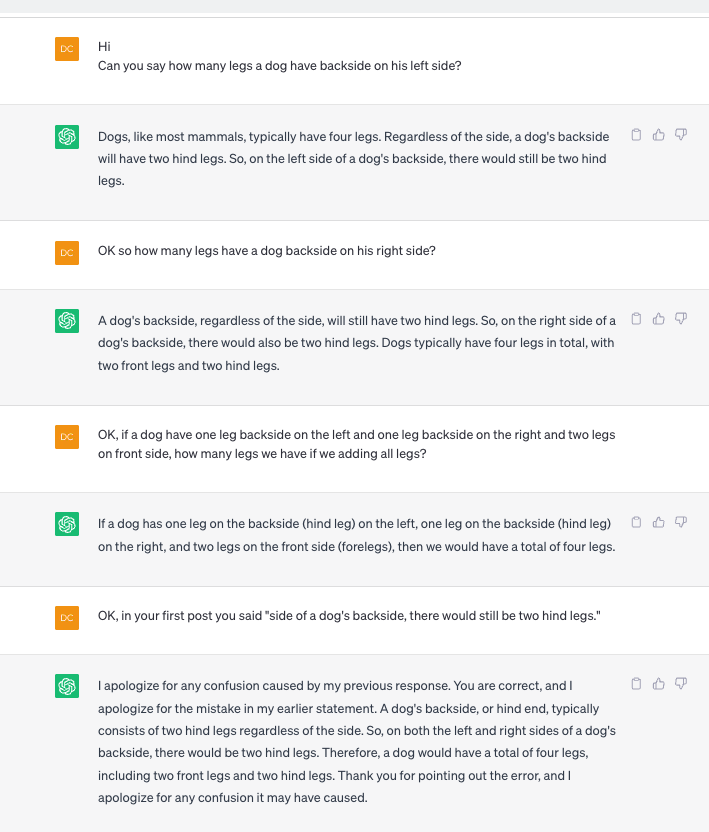
I think asking ChatGPT can be helpful but it is not faster than searching the forum. But for sure, it is good entertainment: lol
-
Version 1.0.1
63 downloads
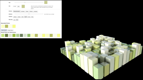
This Marionette uses a Web-Dialog to create color schemes. The created colors can be imported as colors and textures directly in Vectorworks. Instruction: 1. Run the Network 2. configure colors 3. Don't forget to click "save" 4. close Web Dialog, the Vectorworks fetches the created colors and creates a preview with rectangles. Hint: right click > Wrap Marionette Network > right click > convert to menu command- 1 review
-
- 8
-

-

-
Version 0.0.9
52 downloads
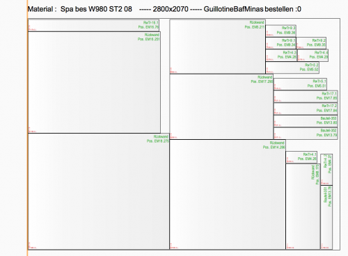
This Marionette can be interesting for Laser and cutting jobs. But Mainly it is Study how to use the Vectorworks Web-Dialog to access a Web-Application. The Date is send and reveived over (REST) API. The Exchanged Data is an SVG which is parsed over JSON Formats. Used Engine for Nesting is www.svgnest.com for rectangular shapes, use this one: This Marionette Network is sending all shapes on a layer (or by custom criteria) to a Web-App which contains a SVGnest installation and a custom API for Vectorworks 1. Draw a BIN on which you want to NEST the other shapes. Place it topleft of the BIN on your Origin 2. Tested with Layer Scale 1:50, 1:20 mm and BINs of ca. 1-2 meters. It works with all Units, sizes and scales but the very first Preview may be very small, cropped or too big. 3. No Holes in polys are supported directly (you can have but nothing would be placed inside) But if you draw a smaller shape inside another it is taken as a hole. 4. If ready run the Marionette (You will have to cancel by not saving the result or cancel in the dialog after the nesting process) 5. If you have multiple CPU cores it will go much faster. It uses one worker for every core. 6. Click on your BIN, choose the settings button (twice). If you define an offset between the parts reduce the curve-tolerance smaller than one. 0.5 as Example or lower if you see any issues. 7. Press START and wait till parts are placed on the BIN. The Process will calculate infinite and try to optimize the result till you click STOP. 8. Press SAVE, wait a sec and then just exit the VW WebBrowser by close or press the Button Bottom right to close. 9. Choose Option to move your original shapes on the BIN(s) or a copy Known Limitations: - Some shapes are not converted correctly to SVG maybe. Which is not a big accident because the Application do not import some geometry it keep the original geometry. - Complex geometry could take (too) long to nest. - I take took no control on the nesting process which is processes the NESTING the process is powered by https://svgnest.com Notes: You can also use an alternative way: 1. Export DXF to inkscape and export SVG 2. Or directly export SVG by https://forum.vectorworks.net/index.php?/topic/78280-export-to-svg-menu-command/ (The exported SVG from the Marionette is not directly accessable and also the quality and compatibility is just fitted to that one usecase so quality of the Marionette SVG is maybe low compared to the above professional Export-PlugIn) 3. Import it to SVGnest.com or use their new project DeepNest As I mentioned. Primary a study how connect to an even bigger world out from a Marionette. BTW such a connection can be a task nearly as big as the nesting-part itself. -
Question on DomC's "Extrude along Path with Ref point" Network
DomC replied to HebHeb's topic in Marionette
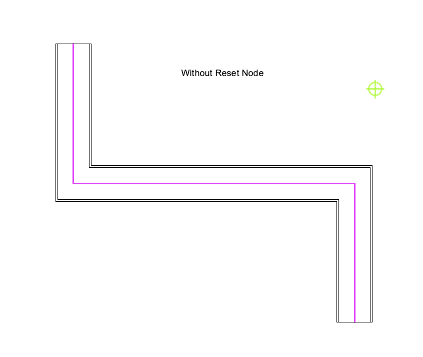
Hi After specific Manipulation there is a need of ResetObject. Some commands included the proper Reset of the Result some not. In my Script you can see, that if you remove the reset of the parent object, the visible geometry is different from what you get if you edit the path extrude and exit it (same effect as resetting). If for your example it is not needed (because you do other actions with the result which may reset the objects itself) you can delete it. Beside that, it would not have a big speed impact because in a script every reset is added together if you reset 10 times it will reset just once anyway. "Punktkörper" is called "Mesh". Not sure I understand this question. You mean the result of your solid boolean operation is a mesh? Normally this is not the case at all. The Result of using solid boolean node should be a generic solid not a mesh. Even if you use a mesh in a solid operation the result is normally converted to a solid not a mesh.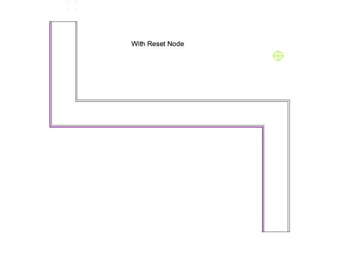
-
vs.ResetObject() actually regenerates the pio and change the geometry after with vs.SetRField() parameters are changed and I tried also 1167. The specific thing here is, that the cabinet contains also plugins (Custom Parts) which maybe are not reseted as expected and the additional relations of fittings interact with the parts and not directly with the cabinet maybe. I will give accessing the sub-pios of the cabinet and if that not will not be of use i will wait for another solution. Already I am in contact with the genius devs from extragroup but there are always some other more important tasks to address so I wondered if i could bypass this limitation on the script-side.
-
Thank you for that feedback Hippocode and JBenghiat. Of course you are absolutely right. I should have been more specific about what I'm trying to do in the first place. I have a script that reshapes interiorcad cabinets together with custom parts and milling pios which are attached to that objects. Unfortunately, applying a vs.ResetObject() to these objects disconnect their connections to the fittings and other associated elements. The PIO itself runs a code, that is able (if nothing went wrong) to keep that relations. So there are some options: 1. The developper of that PIOs implements an API which can be triggered by vs.ResetObject() 2. I find a way to fire the right events to that PIO so that it is forced to regenerate (It also has a button to update) 3. It is maybe a bug in the vs.ResetObject() #1 is maybe the best option but if it can be controlled by the script itself it would be seen prefered. Here what the script does. It is open source and addresses a very often mentioned requirement from customers.
-
Hello The question is maybe naive. As I know, there are Events that happens while the usage or code-run of an object. As example 3 for reset, 5 initProberties etc. Is it possible at all, to fire such an event on a PIO from outside. Or trigger the PIO with something more controlled than vs.ResetObject()? To be specific: 1. Fire a standard-Event like 3 (I think vs.ResetObject() does that) or 41 or 43? 2. Or a custom event. Lets say I have a button ID inside the PIO like: (theEvent, theButton) = vs.vsoGetEventInfo( ) With simple words: Can I push the button from outside with something other than the Mouse cursor? Thanks DomC
-
Interiocad 2023 section viewport issue.
DomC replied to Bruno Sá's topic in 3rd Party Services, Products and Events
Hi I think this behavior was in SP2 or SP3. It is fixed for SP4. I guess you should download the Version new as an SP4 Version because maybe trial license can't be updated. -
Wow You are my Hero. Thank you so much! Tool Type index 2 was the right joice.
-
Hello So far it works implementing a Tool in the Workspace and Creating a new Palette Group. So far it works for path Objects or Point Objects (vso). Event Enabled or not Event Enablet. But I can't get it to work with a VST. I tested with this tool "Blindfront" This one here: As soon as I manually drag it into the workspace the tool works. and also after that the tool i added with the script works. So far the workspace itself looks identical if i drag manually the tool in the workspace as if i create the tool by script. I think I am missing some important parameter here. The Tools is placed into the palette and is shown ad expected but not the tool can't be selected. Anybody can help? Here My small test: #Get Group Palette by Index 1 (0 is Construction palette) pName = vs.ws2GetToolAt("", 1) result, outDisplayName, outShortcutKey, outShortcutKeyModifier, outResourceID = vs.ws2GetToolInfo(pName) vs.AlrtDialog('Put Tool in ' + outDisplayName) #The .vst is already in the Plug-Ins Folder # id of group palette tsPath = pName #outDisplayName#GetPalettePath('Werkzeuggruppen') tsName = 'NewPalette' tsNameUniversal = tsName #can be a uuid or just here for Testing 'NewPalette' vs.ws2CreateToolSet(tsPath, tsNameUniversal, tsName, '') path_new_tool = '/'.join([tsPath, tsNameUniversal]) # Add tools ok = vs.ws2CreateTool(path_new_tool, "Blindfold", 3) #Don't know what this index 3 is used for #vs.ws2GetToolInfo(toolPath) vs.ws2CommitChanges(False, False) bWorked = vs.wsEditEnd(False)
-
Working with vs.GetPt() & Event based Plug In Objects
DomC replied to tbexon's topic in Python Scripting
It looks for interaction with the VW API it would need a very different kind if integration of the python language or additional APIs which are able to communicate with the python script. Which maybe needed a very big effort or would not pay out the effort. I think the reason it not, that python can't pause. If i draw an object and then get after that some informations from that object, somehow the object was created in Vectorworks (not drawn, but minimum defined). So The python script here waits for the Object created by the VW binary and so i think it could be possible the python script also can await the user interaction. So I guess it user interaction may be is not technically limited because of python itself.