SharonP
-
Posts
72 -
Joined
-
Last visited
Content Type
Profiles
Forums
Events
Articles
Marionette
Store
Everything posted by SharonP
-
I really want to use this tool as it is clearly the most efficient way to do a window drawing if you can get it to work properly but I am still having issues. I have tried altering which dimensions show but still can't get the sill of my garage door and the other windows and doors to line up - they are correct in the model. Also, I have one window that is showing correct on the floor plan and in any other 2d or 3d views of the building, but is reversed in the graphic legend, putting the opening sash on the opposite side to where it actually is. I am almost at the point of abandoning the graphic legend too which would be a shame but it is just wasting time at this point. Does anyone have any more ideas for me to try? Thanks Sharon
-
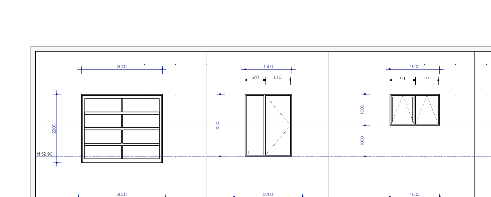
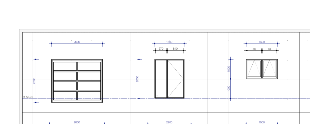
Still hoping someone can help me with this - screenshot attached for clarity. I want my garage door sill to be aligned with the sill of the doors and the floor level. They are both showing correctly aligned in the elevations so not sure why its doing this in my graphic legend.
-
Up until now I have just been adding an annotation regarding window and door numbers and sizes to my plans, but with trying to learn more and use more features of vectorworks I figure this is something I should learn to use as I think I must be able to link this somehow to the new Graphic legend for my door and window schedule. Do people have opinions of which is the better tool to use to do this? Being located in New Zealand I have and use Windoor for all my windows and doors. Thanks Sharon
-
I am trying to use the Graphic legend tool for the first time to do a window and exterior door schedule. A question I am hoping to get help with: How do I have the doors and windows all lined up by floor level? My garage door is 2.2m head height and all the others are 2.0m so currently the garage door is not lined up with all the others. It will be good to get this working as I can already see that it is much faster than how I was previously doing things! Thanks Sharon
-
Does anyone know how to do a windoor object that has one door sliding each way like this but not being cavity sliders? I can't seem to work that one out.
-
I have a bulkhead which I have gone to the trouble of drawing in 3d, and am re-using it in multiple job files for the same client. The problem is that I am having to import the symbol, set up the 3d view and then annotate the viewport each time. Surely there is a better way to do this? It would be easier if I had just drawn it in 2d but surely that isn't what I should be doing? Any ideas please?
-
Thanks so much for your help - the 3d polygon has done almost exactly what I needed ...... ideally I would be able to give it a thickness of 100mm but apart from that......at least I have something resembling a driveway with the contours about right. Always worth asking for help - there are a lot of people more experienced with Vectorworks than I am!
-
slope is significant - the driveway will just be floating in space, I want it for the purposes of making the ground around the split level house look appropriate in some perspective views.
-
I want to create a driveway - in an ideal world all I would need to do is draw a polygon or poly line the shape I want, then pick some points on the perimeter, give them a height and have the shape magically happen...... nothing is quite that simple though. Can anyone tell me which tool I should be trying to use and if what I am hoping for actually exists? Thanks
-
I am trying to draw a 3d polygon and then apply a texture to it - I have successfully drawn the polygon, and when I click on it I can add a texture in the OIP, but then when I view it in 3d or 2d there is no texture to be seen. I have made sure that it is solid in the attributes palette. Is there something I am missing? My 3d polygon is the ground between paths which I have made using extrudes, but I can't do this with an extrude as it is not evenly sloped. Is there a different way I should be doing this? Is it possible to have a 3d polygon with a texture? I'd appreciate any help anyone can give me.
-
I can't help - I wish I could, but I have the same sort of thing happening, but in new files as well. I have just updated a couple of viewports, only to have them disappear - all classes are set to visible. I'm also having trouble with other objects disappearing, and if I change class to another one and then unset and set "none class" then they come back, but not this time. Anyone help? I can't do any annotations to a viewport that I can't see!
-
I am working on a project with 6 houses, which I have set up in separate files, and for some perspectives I have referenced those files into one separate file. In each of the 6 individual files I can view a perfect perspective with hatched walls and roof (hidden line view) but as soon as I look at a 3d view in the referenced file, the roofs all disappear and the walls are transparent. This happens as soon as I use the flyover tool. If I have a look at the front view for example then I have solid walls with no hatch showing (in hidden line) and no roof. Does anyone have any clue as to what is going on? I have wasted about 4 hours so far trying to work this out. I have checked and rechecked all the class and layer visibilities, and this is happening even with all of them set to visible. Even looking at the 6 houses in top view I can see all of the walls instead of the rendered roofs. I have the "use current documents class visibilities" button ticked in each referenced viewport. Anyone got any ideas of what I am missing? I woke up this morning (in NZ) hoping that it had magically fixed itself, but no luck 😕 Sharon
-
I have what is likely to be a very simple fix - just it is not computing with me this morning... I have a very simple symbol - just a cross for spot levels - literally 2 diagonal lines. I want that symbol to take on the colour of the class I have put it on - eg: green for retaining walls, brown for ground level etc.... I have set the colour in the symbol to be class style. I then insert the symbol onto the retaining wall class and it is still black (the colour allocated to the none class that the symbol is made on). Can anyone tell me how to make it do what I want it to? Thanks Sharon
-
I haven't managed to make a 2 step stair either - a bit of a pain when it's not uncommon to have a 300mm step down between floor levels - certainly in the residential buildings I tend to be doing. maybe eventually?.......
-
yeah, they are
-
I have just tried that... and it does. Guess I will have to copy everything to a new file. Thanks for the help. Sharon
-
ok, I have just checked each roof face, and the only geometry in each one was a single polygon, so no stray bits and pieces there. I have just tried creating a new unedited roof on top of the walls, and it creates fine, I can see it in a 2D plan, it has solid fill visible in a 2D plan. I have it selected, and as soon as I go to a 3D view (in this case I have just tried a Right hand view) it disappears-I can still see the blue squares indicating I have something selected and the OIP says it is my roof. The roof is sitting directly on top of the walls, as indicated by the location of the blue squares. I have never had this happen before.... baffling.
-
Nope, very close to origin - numbers are between 0-20000, so almost centred on origin.
-
I have a very straightforward roof for a small house, which I created as a roof, then ungrouped so I could alter one roof face. I have done this many times before with no issues. This time however, I can only see the roof in 2D view, and as soon as I try to look at it in any 3D view it disappears - I can select the roof faces before changing the view and the OIP will say I have 7 roof faces selected, I just can't see any of them. I have tried fit to objects in case the roof faces are in a funny place, but still nothing shows up. Classes are all visible. Any clues? Sharon
-
I have a multi unit residential development that I am currently drawing. There are 6 different small houses on one site, so following suggestions from others I have referenced them into my site plan so that I can have it all up to date, and it is working well.... except that I cannot work out how to control the visibility of the classes within that one file. I have the individual houses on the site plan as viewport in the site design layer, and then when I make the sheet layer with the whole site viewport, I can't seem to control the individual classes properly. Eg, if I don't want to show the walls of the houses, turning off the walls classes don't make them disappear unless I turn them off in the individual house viewports on the site design layer. Then they disappear from all viewports of the full site - which is not what I want - I only want them gone from some sheets, not all..... Here'd hoping that makes sense to someone. Any clues? Thanks Sharon
-
I'm currently using VW2018, but have held off on upgrading to 2019 (even though my computer keeps telling me it is there waiting for me). I assume that DVLP is available in 2018? S
-
This brings up an interesting side point - how to organise multi house developments - this is reasonably new to me, and the first one of 6 houses I have done. I have currently got the houses in separate files, with a site plan as a separate file. I am cutting and pasting from the house files to the site file with each house having a separate design layer. The problem with this arrangement is that if I alter something in the house files I have to remember to change it in the site file. Is there a way to link the files live?
-
I have a residential project that involves 6 different houses on one site. I am using viewports to get the individual houses onto my site plan, ad then dimensioning to the boundary in the main viewport annotation. My issue is that I cannot get the dimensions to snap onto the walls of the individual houses. Anybody got any clue of which mystery setting I need to change? Sharon
-
I have already checked that I have all those classes have the use at creation box unchecked.....and still I have this odd linetype that is different to the one specified in the indoor settings appearing on my RCP. It is very frustrating....
-
I am having issue with indoor classes - I have my doors showing normally on my floor plan (all the lines solid) but when I go to my reflected ceiling plan they are showing with a long dash short dash line style instead of the short dash style that I have selected as the class for the RCP lines. I have looked everywhere that I can think of to see where this linetype is coming from and I have no clue! Does anyone have any ideas of where I can look? Thanks Sharon