


Ron Kwaske
-
Posts
27 -
Joined
-
Last visited
Content Type
Profiles
Forums
Events
Articles
Marionette
Store
Posts posted by Ron Kwaske
-
-
3 hours ago, Jeremiah Russell said:
Is there a way to have more than one stamp on the title block? I.e. we have engineers that we want to show their stamp on the MEP sheets but not our architectural stamp. They are in the same location. Is there a way to control visibility on an individual sheet?
You would need to class the stamps and signatures separately by discipline. I do the same depending on the state I am working in. You can then either manually turn the classes on or off; or, create a script to do it for you. As mentioned in my previous post, I created a script to turn my stamp(s) and signature(s) off and then turn a 'not for construction' label on in its place.
-
Thank you!
-
On 11/18/2022 at 12:57 PM, jnr said:
Ron:
I like your system. Years ago I had wanted to use the software's database to be able to spit out my specs (mostly residential and smaller scale) but alas, got taken out at the knees by the 256 character limit of the database. Worksheets don't have that limit, so I've stuck to old school where I have no connection between the worksheet and the callout or even keynote. I can get the specs on sheets using one long ass worksheet and viewports to get them to fit the page. Not idea especially when the spec changes and you have to adjust the viewport. Would be nice to find a way to automate this instead of copying worksheets from old projects.
thoughts?
I don't link my specs to my callouts- I use them for different purposes.
- I use the description in the classes (organized by csi) for general material notes and call it out via a custom data tag
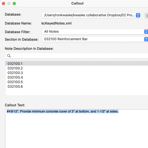
- I use keynotes organized by csi to provide detailed instruction usually in details and section views.
- Finally, I have my specs just as text in a library that I group by section. I manually place and modify them as necessary. I have modified my spec format, still using a 3-part system, but streamlined attempting to make it easier to read. Note that I do not do government work and I am very aware that on small, non-institutional projects, few actually read the specs cover to cover, so I do my best to keep it 'friendly.'
-
 1
1
-
-
8 minutes ago, Ramon PG said:
These floors finishes are in the Floor or Slab layer?
You don't apply the finish to the Space Object and then you have it report to the Finishes Schedule??
I manually enter the finish on the 'room finishes' tab in the space object. I don't know of any way to get a slab object 'talk to' a space object.
-
1
-
-
If I have a floor with many different finishes; I configure my slab so that the top finish is the subfloor. Then, I create extrusions for the floor finish and class them accordingly. This method is really advantageous to detail thresholds if you are careful about the actual thickness of the floor finish.
-
2
-
-
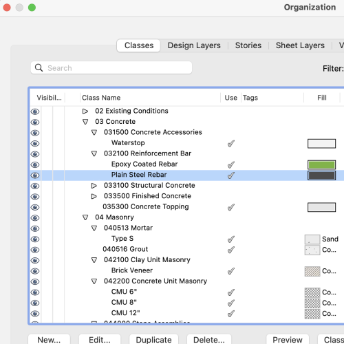
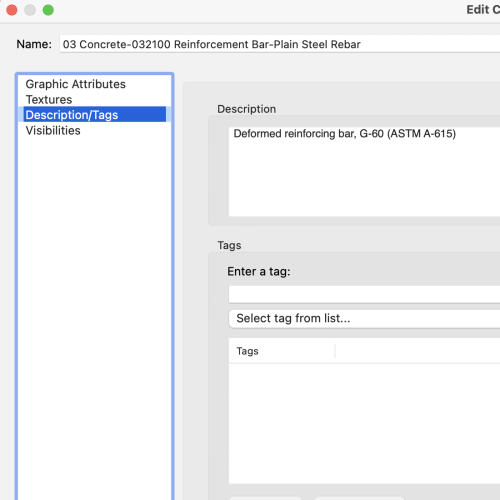
To keep things nice and tidy, and in an attempt to make it easier on the construction end; All of my classes are organized by CSI Masterformat. Within the class, I add a very general description that I can call out via a custom data tag (usually for calling out a material type). Likewise, all of my keynotes are organized by CSI, and I use these for very specific notes to call attention to (usually for calling out a supplier/or equal, or some other minimum criteria, or standard of quality or performance ).
-
I think it easier to just model the stair system. This way, you have complete control, and, you will have very little detailing to do on the back end.
-
15 hours ago, jeff prince said:
Toilets, and sinks, and furniture... oh my.
Inclusion of them will make LAs cry.
From my experience; 3d symbols are often best modeled in VWorks instead of importing from other sources (I have found restaurant equipment notoriously bad to import). A properly modeled symbol using 3d solids and, taking advantage of the correct 'show detail' levels will dramatically decrease processing / rendering time.
-
3
-
-
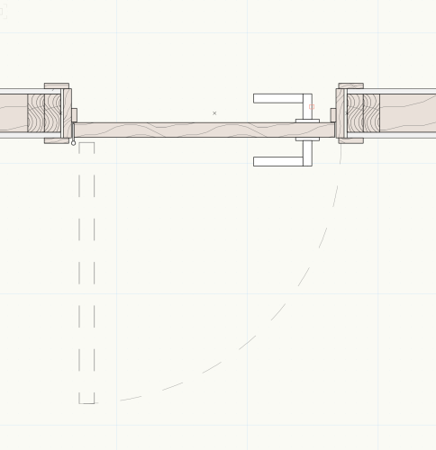
10 hours ago, bennyrc said:
hello,
Was this modeled with 3D tools+symbols?
or was it though the door's OIP
really good detail
100% modeled and then turned into a symbol. I've done this for most of my 'stock' doors - both wood framed and hollow metal.
-
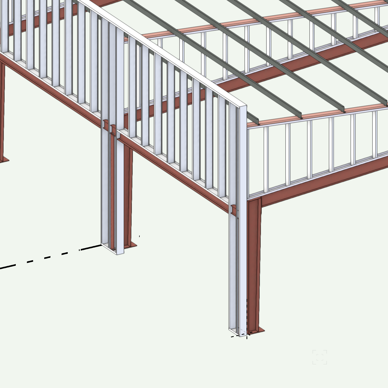
Model it! I do a lot of work with pre-engineered metal buildings - either rehab, or new with unique architectural features. Like timber frame, there is a lot of redundancy, so, I create custom symbols of major components. Be sure to use symbols as much as you can- both for ease of changes; but, also to help manage the file size.

-
2
-
-
- Popular Post
- Popular Post
I use Morpholio and Vectorworks all of the time. I've nearly eliminated all paper from the office, -sketching and taking notes digitally. At the start of a project, I document existing conditions to scale in Morpholio, then, export to PDF and import to Vectorworks. I then scale the sketch, and 'trace' it in Vectorworks. What I really like about this process is that by having the sketch on its own design layer, I also have written notes and observations for immediate reference - really helpful for renovation work. I also use Morpholio to take a photo to then markup exact field conditions. Finally, as a project is being fully developed in Vectorworks - I then like to export to PDF back into Morpholio where I can verify dimensions, and take notes. It becomes a very efficient and circular process.
-
6
-
 1
1
-
On 3/9/2022 at 11:09 AM, Meret said:
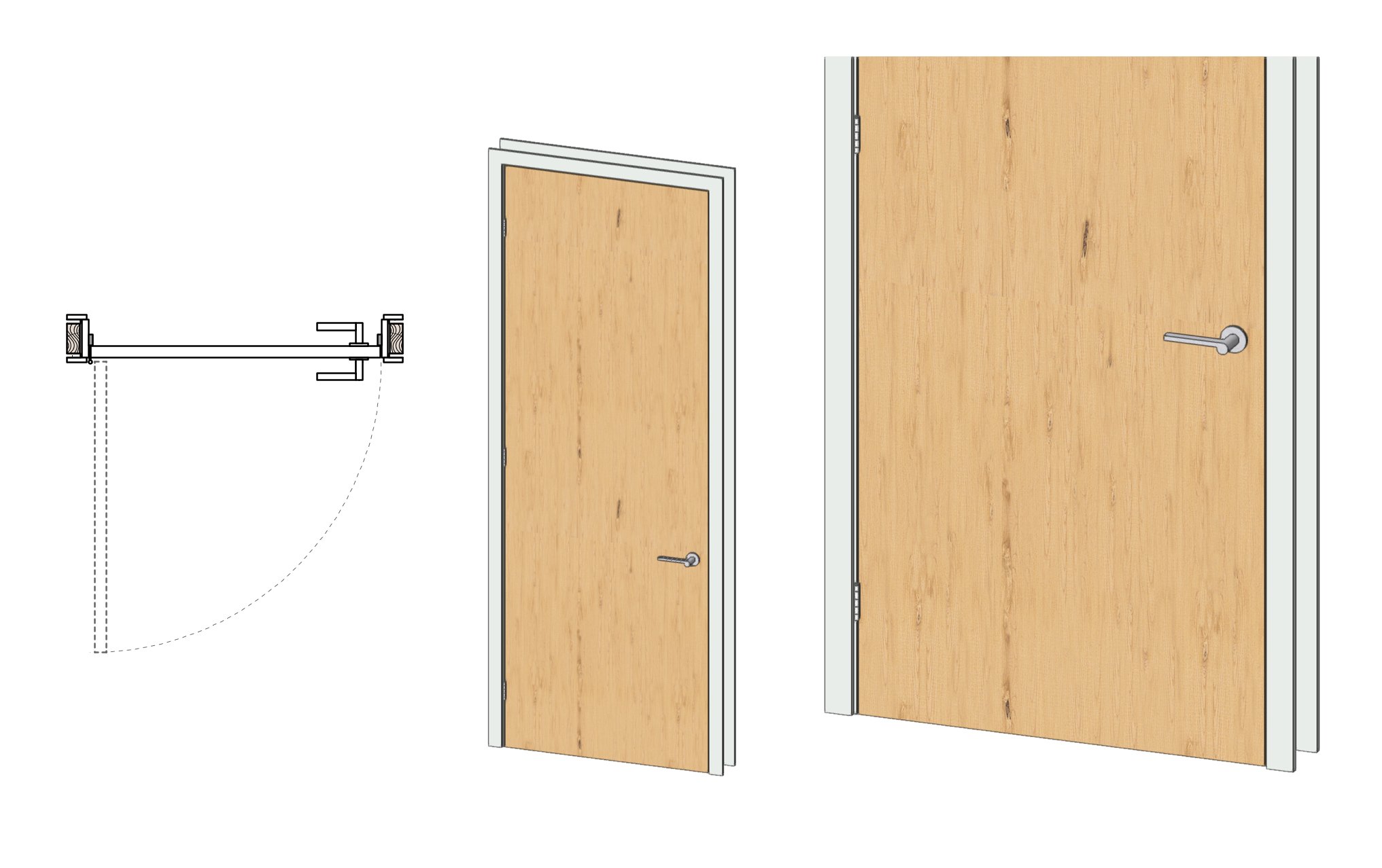
I am looking for a way to set my door trim (as specified in the Door settings) back from the inner edge of the jamb in order to allow room for hinges. I'm attaching a drawing showing which bit.
Thank you!
Meret
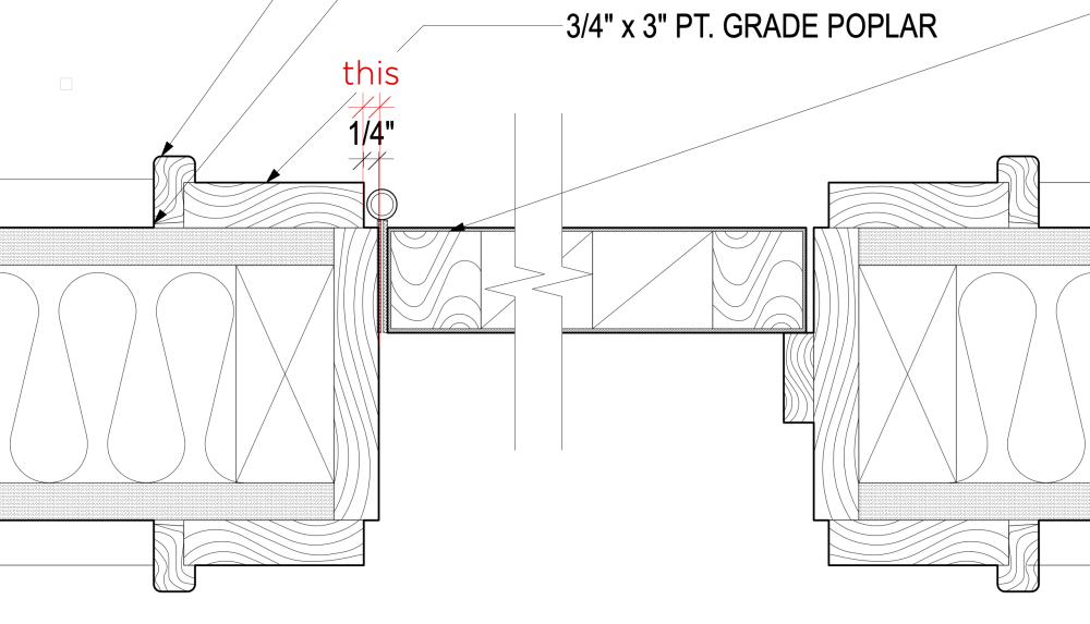
Easiest to just model the door the way that you want. I do agree that doors, windows, etc. should be modeled accurately instead of using antiquated symbols as if we were still drawing by hand.

-
2
-
-
On 1/27/2022 at 2:50 PM, mattryan said:
Hello All
Is there a way to set the curtain wall parameters to space the vertical grid equally between two points?
So if I have a 16'-6" opening and I want 5 panels it will automatically space them correctly?
Thank you
Matt
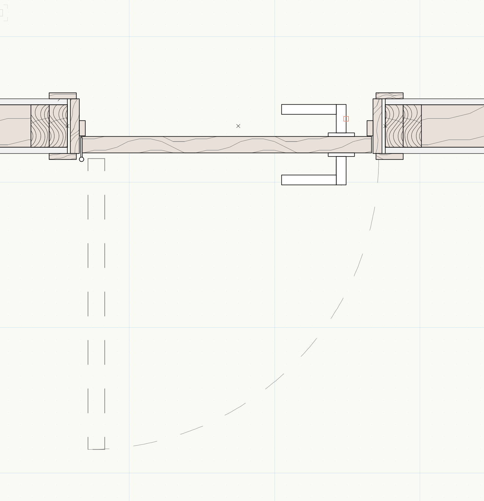
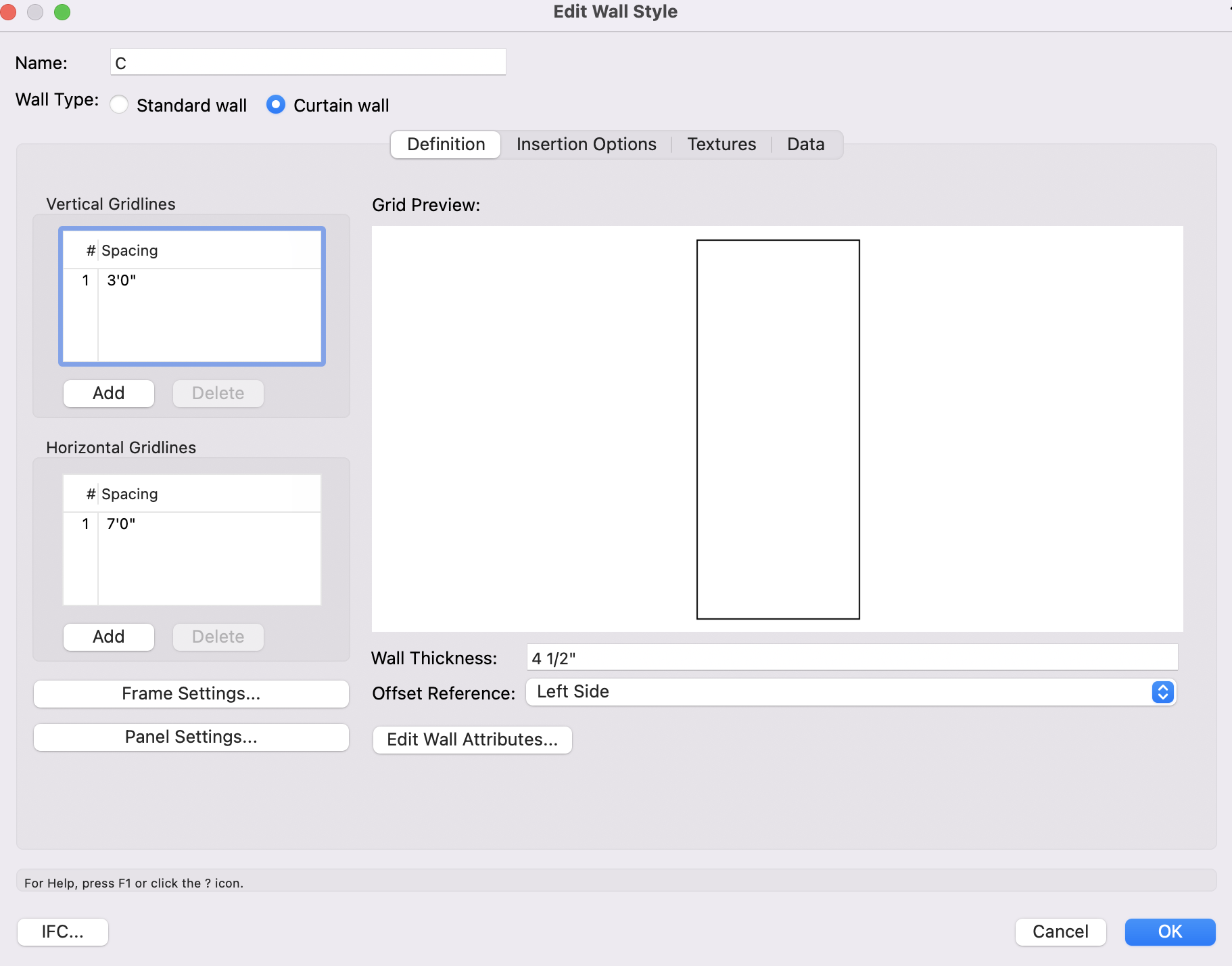
It won't do it automatically; but, you can set the vertical grid for any size panel you want. From the edit wall style of the curtain wall; go to Vertical Gridlines on the far left and change the spacing. If the spacing along the length of wall is not the same, you can add as many as you want.

-
On 2/2/2022 at 10:04 AM, Chris Rogers said:
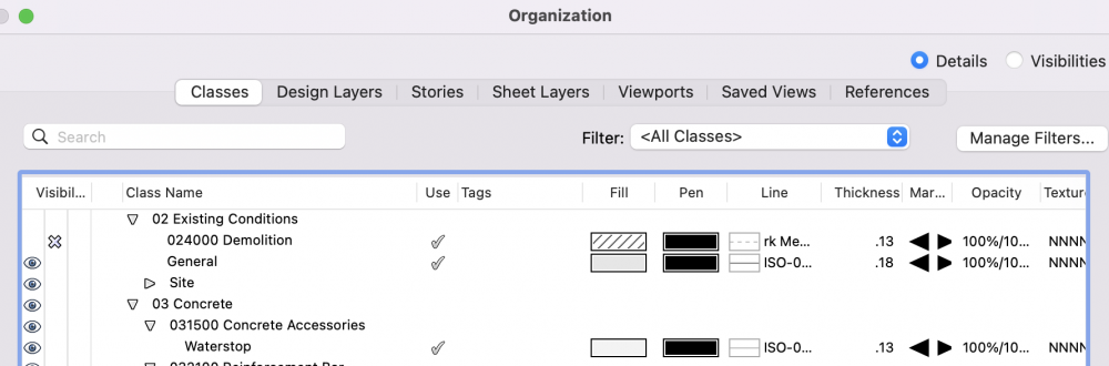
(2D work flow question, probably applied to 3D as well). Has anyone worked up a best practices presentation for dealing with existing construction, demolition, drawings, and new construction? I've tried several methods, and nothings seems to be as simple as it should be. I end up creating Existing, Demo, and New Layers for each level of a building. I create Existing, Demo, and New Wall Types. I create Existing, Demo, and New Classes for 2D objects.
Autoclassed objects like windows and doors are a perpetual pain also. It feels like the entire process is a series of cumbersome workarounds at the moment. Surely someone has an elegant solution?
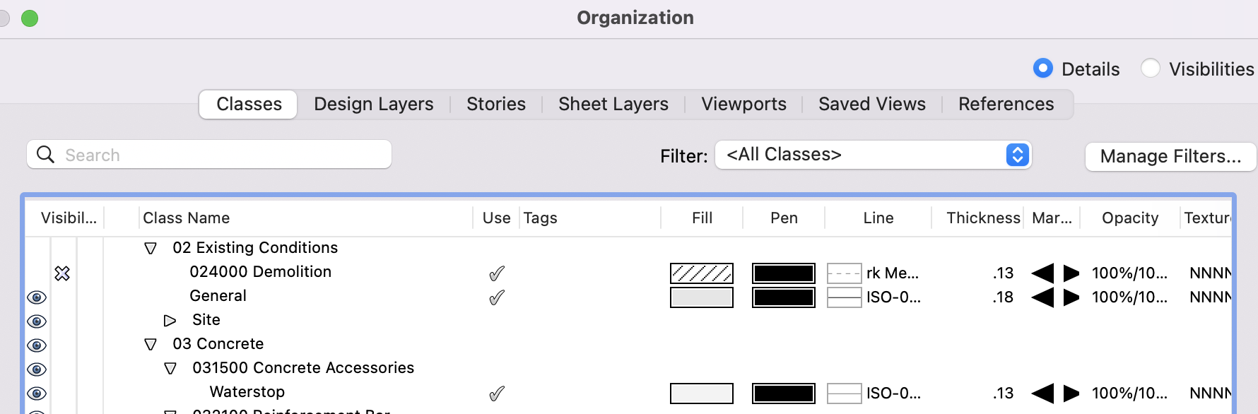
I put ALL items that are existing under one class labeled 02 Existing Conditions - General (this includes everything from walls to fixtures). And then as I begin to demo items I change the class of that item to a Demolition class. eg: a section of wall that needs to be demo-ed: I break the wall in the locations I want it removed, and change the class of the piece I want removed from Existing Conditions to Demolition.
This then allow me to easily create a demo plan by turning the demo class on. For new work, I leave the existing conditions class on, turn demo off, and begin modeling new.
hope this helps.
-
1
-
-
On 2/4/2022 at 8:17 AM, Shortnort said:
I understand the logic of that. But with today's technology, if someone wants to"steal" your stamp it is a very simple process of scanning and pasting... Even years ago people would copy and sticky back onto documents.
As a small business and time being a premium, it just seems that there should be a much simpler way to turn on and off the seal
I am still having problems importing the seal into the titleblock on another layer. I have spent hours now trying to get this to work and the image I import is huge with a stamp attached even though the graphics I used does have that stamp. I will just find a work around.
Thank you for your time and patience.
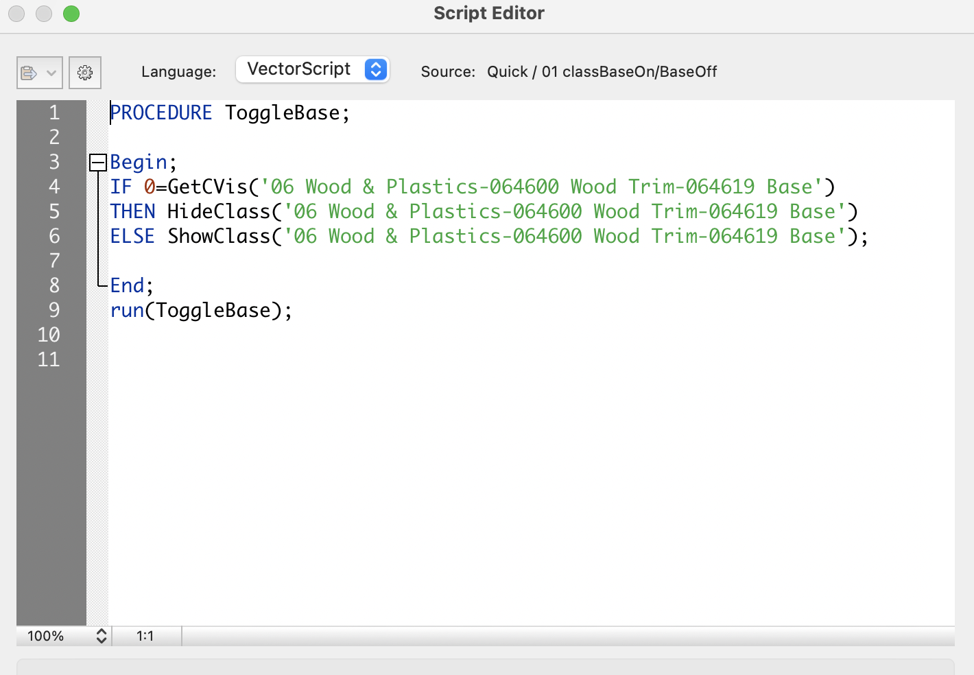
I have my signature and stamp on their own class within the title block layout.
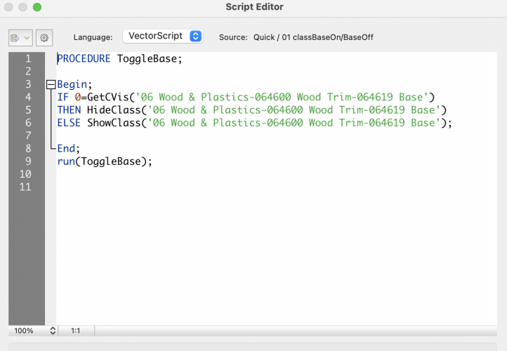
I then have written a quick script that I run before printing to PDF that will either turn the signature and stamp on, or, turn it off. When it is turned off, a 'NOT FOR CONSTRUCTION' label turns on in place of the stamp. One mouse click before printing gives me peace of mind that the drawing set is either issued or not.
-
3
-
-
On 12/1/2021 at 1:06 PM, luiza_finger said:
Hi, there! So I am 6 years late to this thread!
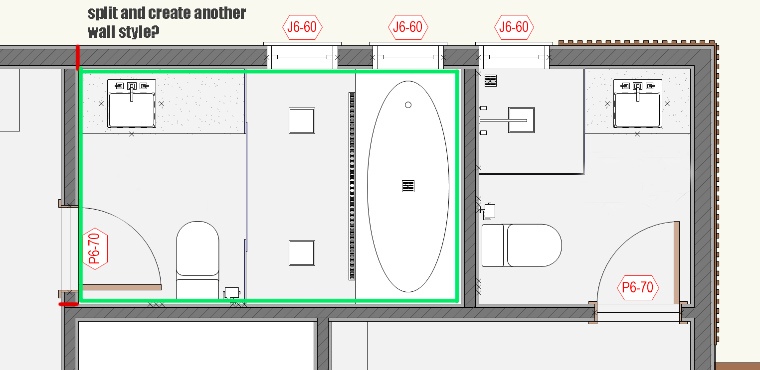
Here I am wondering what would be the recomended workflow whenever there's a wall that has tiles in the bathroom and plaster+paint in the bedroom.I feel like simply splitting the walls and replacing with a new wall style with tiles. However, it does seems to come with a cost later on in case I need to move my walls.
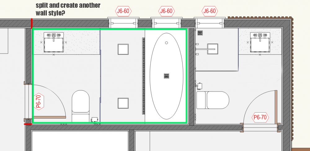
In addition, would you create a new wall style for every tile texture in the project? Say I have 10 different tiles in the project 😁, should I duplicate my wall styles to each one of them? Seems cumbersome, but could be handy later on worksheet schedules...
Looking forward to suggestions.
Thanks, Luiza!If your policy is to keep the model 'clean' and use the data (information) to the fullest extent of the model's abilities, then I would create separate wall types and split the wall as you suggested This way, my wall and finish schedule automatically updates eliminating coordination (I admit that it can get messy if walls need to move; but, it is much better to keep things organized). If it is a really small project where I can get by with just some notes added manually, then I make a 3/8" extrusion next to the wall and put it on a 'tile' class for rendering purposes (this can get messy and hard to find if you need to go back to the project at a later date.)
-
1
-
-
On 8/16/2021 at 8:34 AM, taoist said:
1. Viewports would require switching in and out of design layer
2. Yes to sentence #3, #4.
3. Saved views are not dynamic.
Guess will have to live with it for now.
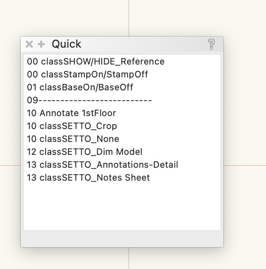
I had a similar issue with baseboard. I like to to show it in elevation, section, and 3d; but certainly not in plan. So, rather than trying to constantly find the class that it is on an turn it on or off; I wrote a script that toggles it on or off. I keep a small script pallet of my most used scripts always floating on top of my workspace to increase efficiency (I titled the pallet 'Quick'). Admittedly, there is one step of double clicking it as you change views; however, I have grown to really like the flexibility of it. You could modify the script so that if you double click it from a custom view, it goes into plan view and shuts off the classes you don't want (siding & GWB), double click it again and it turns the classes back on and initiates the flyover tool. Just a thought..
-
On 8/12/2021 at 12:20 PM, grant_PD said:
Is there any way with the door tool to add the stop onto the jamb of the door? I've always added it manually but thought there would be a setting for it somewhere...
Make your own door and save it as a symbol. (They will look better.)

-
On 7/27/2021 at 3:28 PM, BG said:
Just wondering how others are drawing 3D plumbing schematics? We have been using the HVAC tools, but they aren't overly user friendly. They don't automatically join, the vertical ducts can't be dragged to change their height, there are no falls on the straight ducts etc etc
Any improvement on this would be welcomed.
Thanks
For a schematic- use a 3d polyline and then 'extrude along path' with the desired diameter. For more detailed DWV work, I have 3d symbols for most cast iron / pvc fittings and I extrude lengths of various sized pipe.
-
On 7/22/2021 at 11:54 AM, David Poiron said:
We've been using FileMaker Pro to create an in-house database of products but linking it directly to anything in VW is proving to be a challenge. Each of our products has a serial number that we would like to link to objects in VW but we are at a loss of how to do so reliably - we've tried ODBC before but as one VW staffer mentioned to us recently that can be a brittle connection. In addition to the serial number our system has a three letter code for each section of the North American MasterFormat System (as that is easier to read than a bunch of section numbers), followed by a number for the object in that section for that project: say DHW-01 for a door handle for a particular project. The number changes depending on the project but the serial number (a 6 digit number) does not. It would be great to use data tags to extract the information from an object but it is difficult to make links to the extent we would like; even for symbols there does not appear to be a way to assign a serial number to the symbol that is persistent across all instances of the symbol, which is needed to make a link to an outside database. I am curious about the use of VWs Database Manager for this. I would like more information on @shorter s exporting and importing routines if he is willing to share.
You might consider creating a custom Record Format along with a custom Data Tag to recognize it- the data can then be extracted to a worksheet. I would recommend creating unique symbols for each product along with the custom data tag already attached. Any data that needs to be modified is then done in the Data section of the object info pallet after the symbol has been placed. I've been successfully doing with this doors, hardware, and lighting components (its a laborious process, but so far, worth it because I can provide a lot of pertinent information that the contractor will actually read and use.)
-
- Popular Post
- Popular Post
On 5/29/2021 at 1:35 PM, line-weight said:It seems to me that 95% of the problems with levels / stories are to do with user interface design. The basic thing is fairly sound and not actually all that complex. But as usual, VW somehow manages to implement it in a way that is almost as if it's deliberately designed to be as confusing as possible.
One way I found to get around the 'confusing aspect' of using stories & level type is to create a spreadsheet to help simplify the math. I use stories with a finished floor level (FF) and a Joist Bearing level. On the left side of the spreadsheet, enter desired floor to ceiling heights, along with the thickness of the floor/ceiling assembly. On the right, it gives me all of the elevations I need to enter.
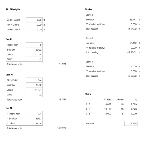
(I also custom build the stairs instead of using the stair tool, so I have the spreadsheet calculate that as well - shown bottom right).
-
6
-
The problem here, for me anyway, is not that Vectorworks is not currently compatible with Mojave; or that some of us have upgraded to Mojave without realizing the incompatibility- It is Vectorworks' failure to communicate.
If Vectorworks can send an email notifying me that 2019 is here and available; it also could have sent an email urging users not to upgrade to Mojave.
-
2
-
-
1 hour ago, Barrett H said:
I updated to Mojave and now both VW2018 and 2019 are unusable. The biggest issue is I can't even select the text tool without a total freeze and need to force quit. Not sure what to do now that I'm in the middle of many projects and need to work on the drawings. (also crashes with opening a blank new file and trying to create any text) Downgrading back to High Sierra means wiping your entire HD -- all that for VW to work. I do not have the time or patch for that right now. To say I'm disappointed would be an understatement. In what we spend annually on this software for it not to work with new macOS versions when they have been in beta for many months is beyond frustrating.
Concur. I am in a similar boat: either use an old computer in the back of my office; or wipe my entire HD, downgrade, and start over (which is another day of lost productivity).
-
1
-
-
- Popular Post
- Popular Post
I upgraded my laptop to Mojave this morning only to find that both Vectorworks 2018 and 2019 are not compatible. It never occurred to me to check the Vectorworks forums to verify compatibility; and frankly, I should not have to.
A simple email from Vectorworks with their recommendation not to upgrade to Mojave at this time would have curtailed this problem. Now, I have to either not use my new MacBook Pro until a Service Pack comes out; OR, find a way to revert back to High Sierra, which appears to be much easier said than done..
Very, very disapointed.
-
6
-
 1
1


Architect's Sign Seal on Sheets - Easiest Method?
in Architecture
Posted · Edited by Ron Kwaske
I would manually class all the stamps separately: eg: Stamps-Arch, Stamps-SE, Stamps-PE, Stamps-CE. And then have only the respective stamp class turned on, on its coordinating title block. To make life easier, you could then create a script to turn them on or off as needed.