Ron Kwaske
-
Posts
27 -
Joined
-
Last visited
Content Type
Profiles
Forums
Events
Articles
Marionette
Store
Everything posted by Ron Kwaske
-

Architect's Sign Seal on Sheets - Easiest Method?
Ron Kwaske replied to Shortnort's topic in Architecture
I would manually class all the stamps separately: eg: Stamps-Arch, Stamps-SE, Stamps-PE, Stamps-CE. And then have only the respective stamp class turned on, on its coordinating title block. To make life easier, you could then create a script to turn them on or off as needed. -
Architect's Sign Seal on Sheets - Easiest Method?
Ron Kwaske replied to Shortnort's topic in Architecture
You would need to class the stamps and signatures separately by discipline. I do the same depending on the state I am working in. You can then either manually turn the classes on or off; or, create a script to do it for you. As mentioned in my previous post, I created a script to turn my stamp(s) and signature(s) off and then turn a 'not for construction' label on in its place. -
Thank you!
-
Schedule of Values (Contractor Budget)
Ron Kwaske replied to Scott Schwartz, AIA's topic in Architecture
I don't link my specs to my callouts- I use them for different purposes. - I use the description in the classes (organized by csi) for general material notes and call it out via a custom data tag - I use keynotes organized by csi to provide detailed instruction usually in details and section views. - Finally, I have my specs just as text in a library that I group by section. I manually place and modify them as necessary. I have modified my spec format, still using a 3-part system, but streamlined attempting to make it easier to read. Note that I do not do government work and I am very aware that on small, non-institutional projects, few actually read the specs cover to cover, so I do my best to keep it 'friendly.'
-
I manually enter the finish on the 'room finishes' tab in the space object. I don't know of any way to get a slab object 'talk to' a space object.
-
If I have a floor with many different finishes; I configure my slab so that the top finish is the subfloor. Then, I create extrusions for the floor finish and class them accordingly. This method is really advantageous to detail thresholds if you are careful about the actual thickness of the floor finish.
-
Schedule of Values (Contractor Budget)
Ron Kwaske replied to Scott Schwartz, AIA's topic in Architecture
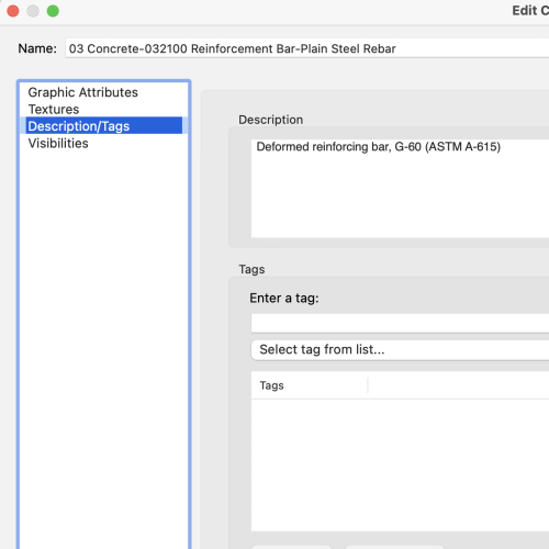
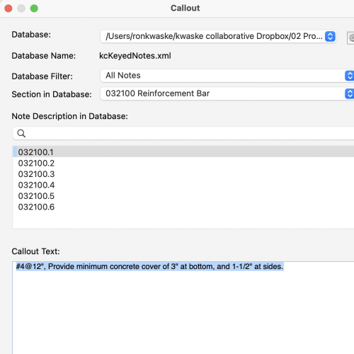
To keep things nice and tidy, and in an attempt to make it easier on the construction end; All of my classes are organized by CSI Masterformat. Within the class, I add a very general description that I can call out via a custom data tag (usually for calling out a material type). Likewise, all of my keynotes are organized by CSI, and I use these for very specific notes to call attention to (usually for calling out a supplier/or equal, or some other minimum criteria, or standard of quality or performance ).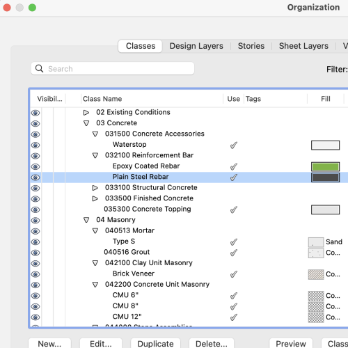
-
I think it easier to just model the stair system. This way, you have complete control, and, you will have very little detailing to do on the back end.
-
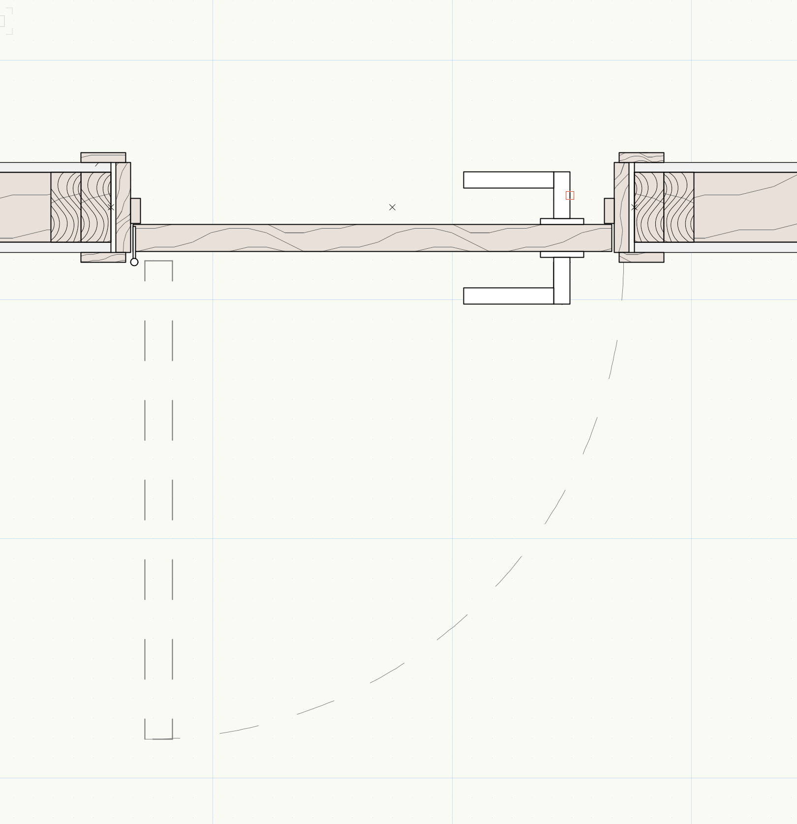
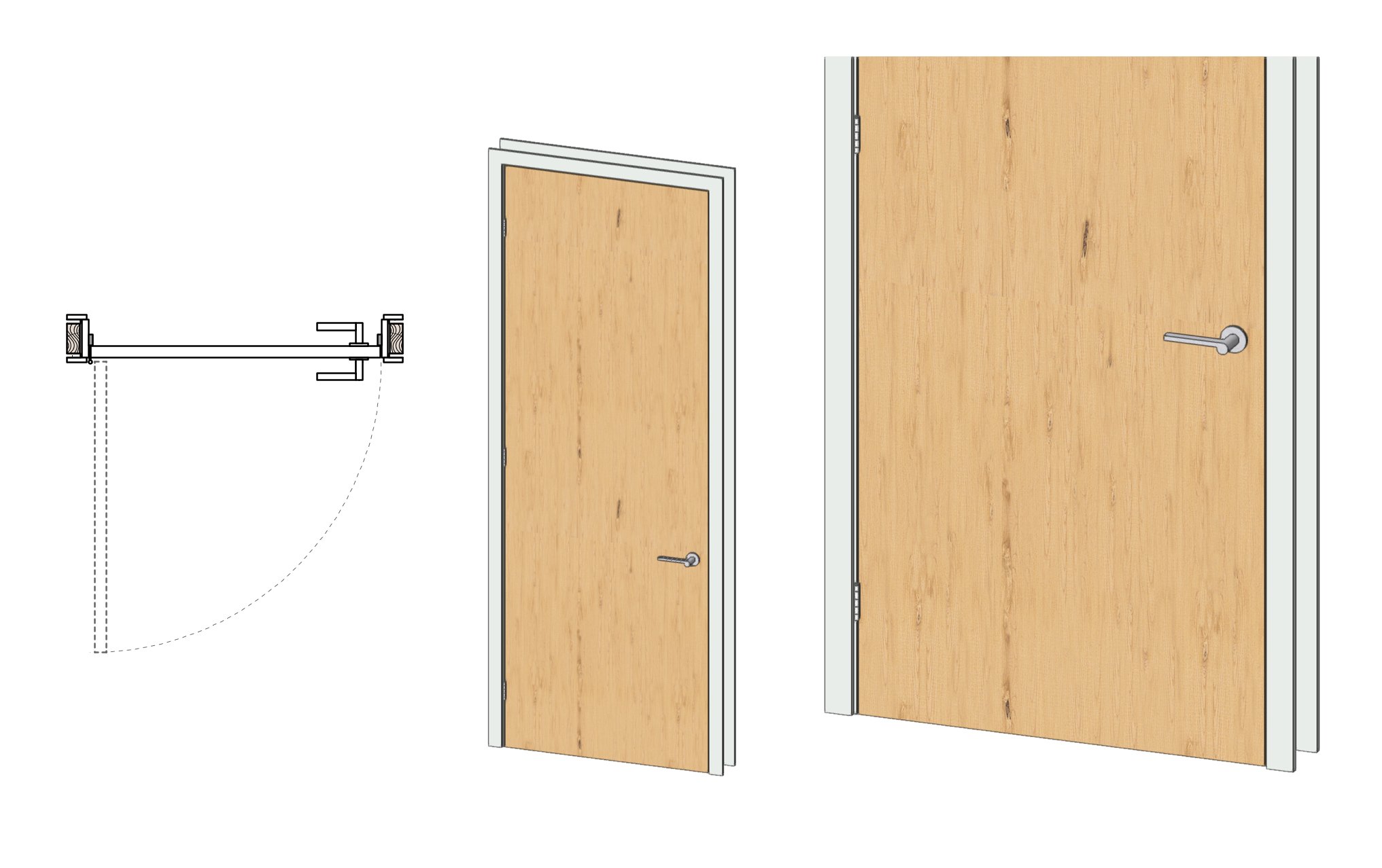
Offsetting the rim from the jamb to make room for hinge in BIM.
Ron Kwaske replied to Meret's topic in Architecture
From my experience; 3d symbols are often best modeled in VWorks instead of importing from other sources (I have found restaurant equipment notoriously bad to import). A properly modeled symbol using 3d solids and, taking advantage of the correct 'show detail' levels will dramatically decrease processing / rendering time. -
Offsetting the rim from the jamb to make room for hinge in BIM.
Ron Kwaske replied to Meret's topic in Architecture
100% modeled and then turned into a symbol. I've done this for most of my 'stock' doors - both wood framed and hollow metal. -
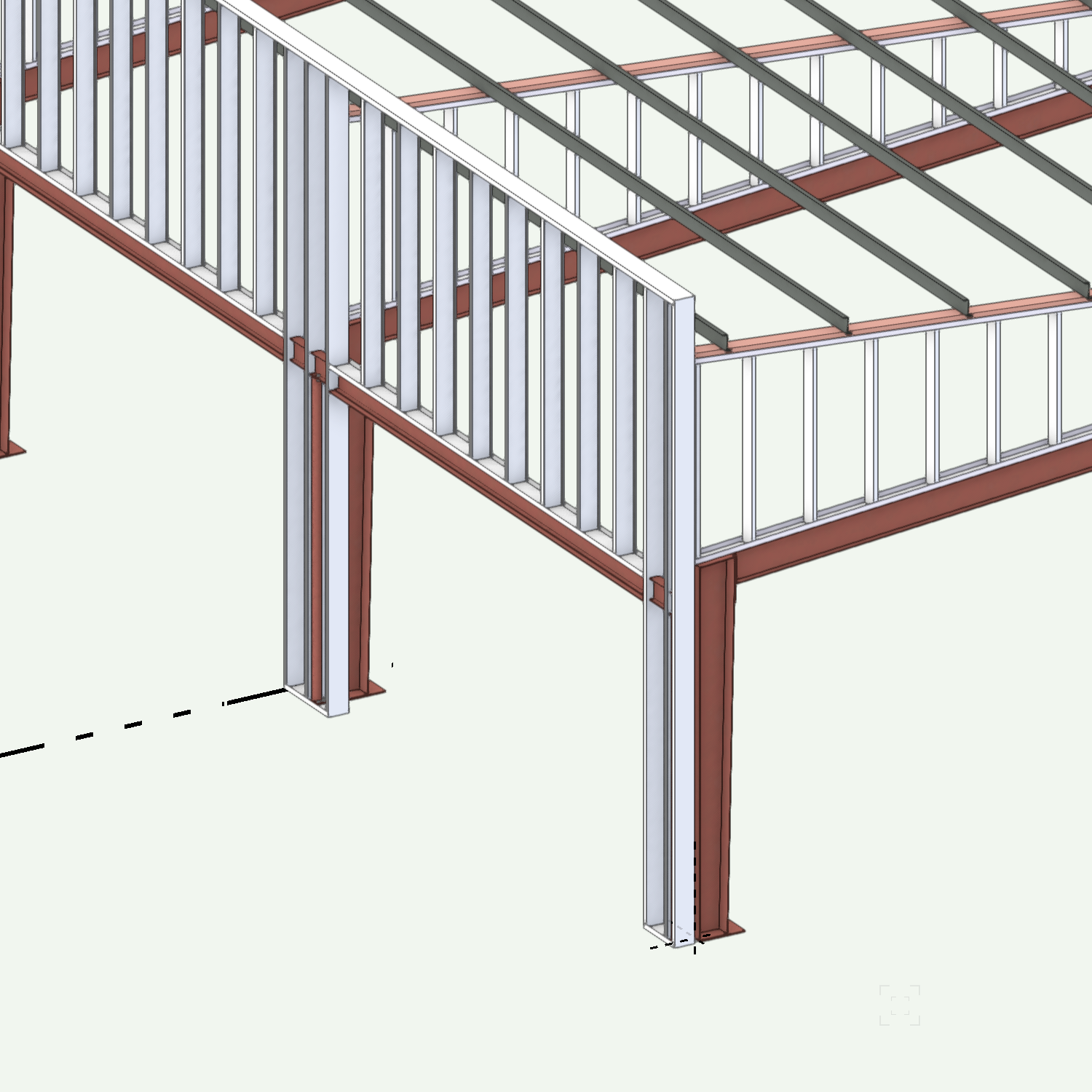
Model it! I do a lot of work with pre-engineered metal buildings - either rehab, or new with unique architectural features. Like timber frame, there is a lot of redundancy, so, I create custom symbols of major components. Be sure to use symbols as much as you can- both for ease of changes; but, also to help manage the file size.

-
I use Morpholio and Vectorworks all of the time. I've nearly eliminated all paper from the office, -sketching and taking notes digitally. At the start of a project, I document existing conditions to scale in Morpholio, then, export to PDF and import to Vectorworks. I then scale the sketch, and 'trace' it in Vectorworks. What I really like about this process is that by having the sketch on its own design layer, I also have written notes and observations for immediate reference - really helpful for renovation work. I also use Morpholio to take a photo to then markup exact field conditions. Finally, as a project is being fully developed in Vectorworks - I then like to export to PDF back into Morpholio where I can verify dimensions, and take notes. It becomes a very efficient and circular process. Sketch.pdf hvvac.pdf Markup.pdf
-
Offsetting the rim from the jamb to make room for hinge in BIM.
Ron Kwaske replied to Meret's topic in Architecture
Easiest to just model the door the way that you want. I do agree that doors, windows, etc. should be modeled accurately instead of using antiquated symbols as if we were still drawing by hand.

-
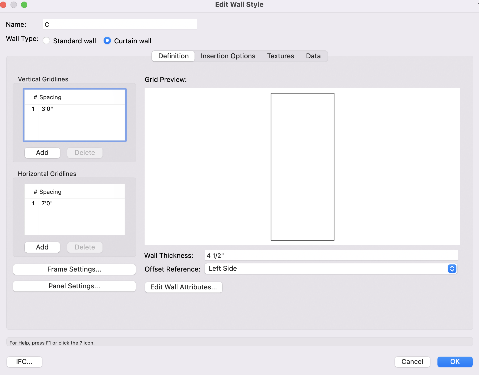
It won't do it automatically; but, you can set the vertical grid for any size panel you want. From the edit wall style of the curtain wall; go to Vertical Gridlines on the far left and change the spacing. If the spacing along the length of wall is not the same, you can add as many as you want.

-
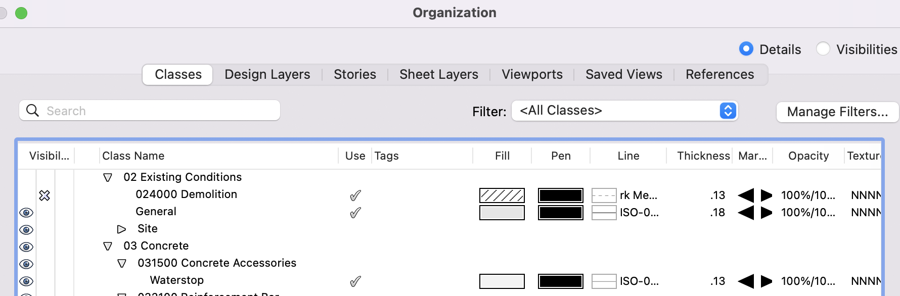
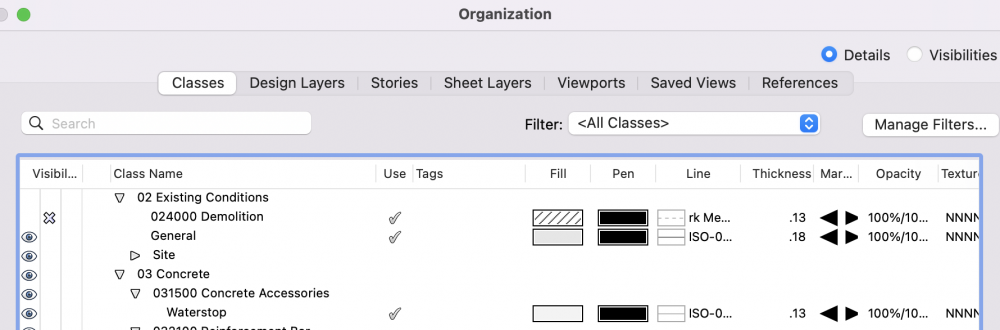
I put ALL items that are existing under one class labeled 02 Existing Conditions - General (this includes everything from walls to fixtures). And then as I begin to demo items I change the class of that item to a Demolition class. eg: a section of wall that needs to be demo-ed: I break the wall in the locations I want it removed, and change the class of the piece I want removed from Existing Conditions to Demolition. This then allow me to easily create a demo plan by turning the demo class on. For new work, I leave the existing conditions class on, turn demo off, and begin modeling new. hope this helps.
-
Architect's Sign Seal on Sheets - Easiest Method?
Ron Kwaske replied to Shortnort's topic in Architecture
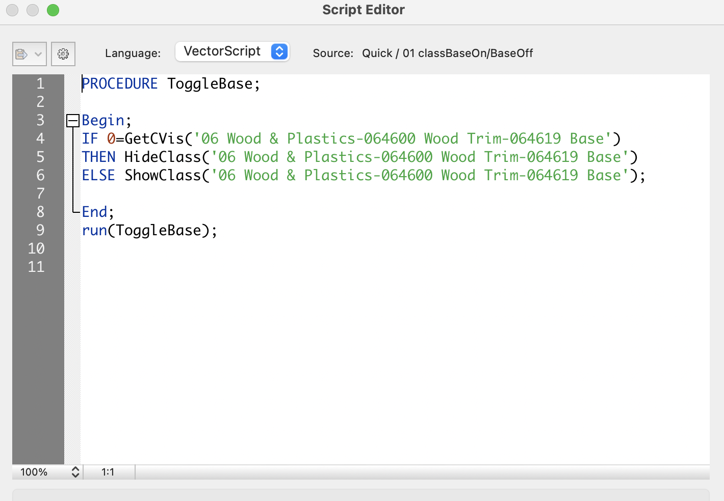
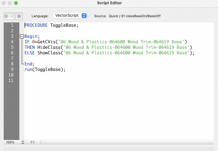
I have my signature and stamp on their own class within the title block layout. I then have written a quick script that I run before printing to PDF that will either turn the signature and stamp on, or, turn it off. When it is turned off, a 'NOT FOR CONSTRUCTION' label turns on in place of the stamp. One mouse click before printing gives me peace of mind that the drawing set is either issued or not. -
If your policy is to keep the model 'clean' and use the data (information) to the fullest extent of the model's abilities, then I would create separate wall types and split the wall as you suggested This way, my wall and finish schedule automatically updates eliminating coordination (I admit that it can get messy if walls need to move; but, it is much better to keep things organized). If it is a really small project where I can get by with just some notes added manually, then I make a 3/8" extrusion next to the wall and put it on a 'tile' class for rendering purposes (this can get messy and hard to find if you need to go back to the project at a later date.)
-
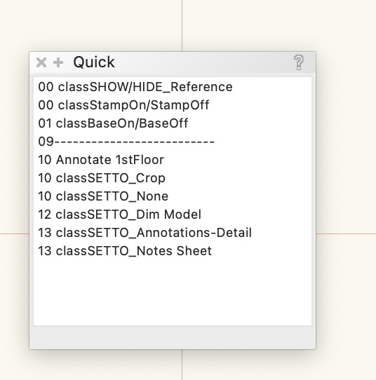
I had a similar issue with baseboard. I like to to show it in elevation, section, and 3d; but certainly not in plan. So, rather than trying to constantly find the class that it is on an turn it on or off; I wrote a script that toggles it on or off. I keep a small script pallet of my most used scripts always floating on top of my workspace to increase efficiency (I titled the pallet 'Quick'). Admittedly, there is one step of double clicking it as you change views; however, I have grown to really like the flexibility of it. You could modify the script so that if you double click it from a custom view, it goes into plan view and shuts off the classes you don't want (siding & GWB), double click it again and it turns the classes back on and initiates the flyover tool. Just a thought..
-
Make your own door and save it as a symbol. (They will look better.)

-
For a schematic- use a 3d polyline and then 'extrude along path' with the desired diameter. For more detailed DWV work, I have 3d symbols for most cast iron / pvc fittings and I extrude lengths of various sized pipe.
-
What specifications software systems are you using?
Ron Kwaske replied to LDraminski's topic in Architecture
You might consider creating a custom Record Format along with a custom Data Tag to recognize it- the data can then be extracted to a worksheet. I would recommend creating unique symbols for each product along with the custom data tag already attached. Any data that needs to be modified is then done in the Data section of the object info pallet after the symbol has been placed. I've been successfully doing with this doors, hardware, and lighting components (its a laborious process, but so far, worth it because I can provide a lot of pertinent information that the contractor will actually read and use.) -
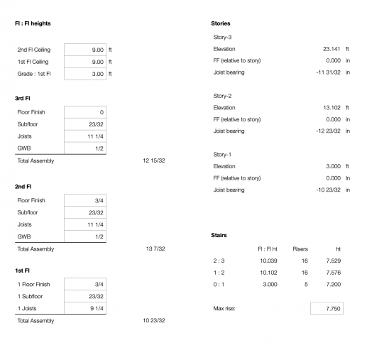
One way I found to get around the 'confusing aspect' of using stories & level type is to create a spreadsheet to help simplify the math. I use stories with a finished floor level (FF) and a Joist Bearing level. On the left side of the spreadsheet, enter desired floor to ceiling heights, along with the thickness of the floor/ceiling assembly. On the right, it gives me all of the elevations I need to enter. (I also custom build the stairs instead of using the stair tool, so I have the spreadsheet calculate that as well - shown bottom right).
-
The problem here, for me anyway, is not that Vectorworks is not currently compatible with Mojave; or that some of us have upgraded to Mojave without realizing the incompatibility- It is Vectorworks' failure to communicate. If Vectorworks can send an email notifying me that 2019 is here and available; it also could have sent an email urging users not to upgrade to Mojave.
-
Concur. I am in a similar boat: either use an old computer in the back of my office; or wipe my entire HD, downgrade, and start over (which is another day of lost productivity).
-
I upgraded my laptop to Mojave this morning only to find that both Vectorworks 2018 and 2019 are not compatible. It never occurred to me to check the Vectorworks forums to verify compatibility; and frankly, I should not have to. A simple email from Vectorworks with their recommendation not to upgrade to Mojave at this time would have curtailed this problem. Now, I have to either not use my new MacBook Pro until a Service Pack comes out; OR, find a way to revert back to High Sierra, which appears to be much easier said than done.. Very, very disapointed.