


Conrad P
-
Posts
93 -
Joined
-
Last visited
Content Type
Profiles
Forums
Events
Articles
Marionette
Store
Posts posted by Conrad P
-
-
Hi Daniel,
Finding names for stuff can be a tough call as we expand across more design disciplines.
Regarding your question, both the Device Builder and Service Select symbol libraries are valid approaches and in a way serve different needs.
Device Builder is better suited to creating schematic devices because it constructs your device out of data preserving your particular house style. I could see some fun improvements to DB like adding richer graphics assuming we can store these somehow in the database.
You can of course save devices as symbols and share them with your colleagues. But for us distributing schematic device symbols worldwide would run into the problem that designers have different preferences regarding colors, fonts, units, grid settings and therefore socket spacing. Device Builder doesn't have this problem.
Where symbol libraries really come into their own is for modelling physical equipment items. Already we are working to leverage Vectorworks existing symbol content and integrate it with ConnectCAD Equipment objects to provide accurate, rich graphics. Moving forward I can see the day where we have physical equipment symbols available to complement Device Builder makes and models.
Thanks for getting me thinking about this. As ever, it's great talking with you guys.
Conrad
-
Hi Max,
Thanks from me also. We'll get that file sent over to us and check on this.
Conrad
-
Hi Daniel,
Your question makes absolute sense to me 🙂 You want ConnectCAD and Spotlight to talk to each other - and I think that's a great idea. I'll brainstorm this with the Spotlight guys and see where we can take this.
Conrad
-
 1
1
-
-
Hi Dima
At the moment the limit is 8 custom parameters. We'll be looking at making these unlimited in a future version. You can play with which ones are text fields and which are choice lists. If a choice list is present then the parameter will be formatted as a dropdown, if it is not present then it is a edit text.
Conrad
-
knallfrosch21 - please contact VW Sales in the US or your local distributor.
-
Hi Mike,
We're always working to improve ConnectCAD. Hooking up with Vectorworks has only accelerated that process. In this last year we have completed a huge transition from being primarily based in Vectorscript to becoming a fully SDK-based plug-in. Of course there have been some changes. We wouldn't be doing the new technology any justice if there weren't. You do well to draw my attention to anything you see as an omission. You appreciate that we have taken the opportunity to prune away some dead wood. Please let me know in as much detail as you can regarding any facilities you had, that you actually miss now.
Publishing our roadmap here is something I would have to clear with my management. But I can tell you that we have a lot of ideas in the pipeline.
There will always be an infinite list of things a piece of software doesn't do !!! Perhaps it's a tribute to how great software has become that our expectations are limitless!
Conrad
-
Did you know...
that the Spotlight Numbering command also works in ConnectCAD. Here's Jim Woodward's guide.
Conrad
-
4
-
-
Another of the beauties of being embedded in Vectorworks. The synergies! The ConnectCAD numbering command also provides automated numbering based on the names of your devices and sockets or any other parameter you care to use. All this choice, thanks to it all being in the same environment.
C
-
Did you know...
the whole story about special device names in ConnectCAD and what they all mean?
-
1
-
-
-
1
-
-
Did you know...
how Connector Panel devices and Equipment Items work together in ConnectCAD 2020? Here's the definitive guide.
-
1
-
-
Sorry Art that doesn't work for SDK plug-ins.
Conrad
-
Hi Ido
At the moment I would suggest abbreviating the names and make/models a bit, and using Text Align Left or Right to maximise the available space. We will make Text menu drive the Name parameter in a forthcoming release to help some more.
Best
Conrad
-
Well, that's interesting... yes you have a point. You could partly alleviate this by choosing Text Align Left or Right. After that it becomes difficult. We are having a think about this...
Conrad
-
Yes that's true but you can't rotate it w.r.t. the circuit path which I think was what Dmitry wanted.
-
Hi Dmitry
I have a feeling that you are using a layer scale that is not 1:1 which might account for the strange text sizes. It's best when starting out to begin from the ConnectCAD template and then branch out from there as you get more familiar. At the moment ConnectCAD schematics should be drawn at 1:1 scale. Essentially schematics are Not To Scale drawings so it shouldn't be a problem to have them at 1:1. Supporting other scales is in our future plans but the truth is that the benefit is quite smal in the end for the amount of work. Ok, so I digressed a bit...
Now to answer your question. No you can't move the cable number, it's part of the Circuit object and the orientation is determined by the Circuit path.
Hope that helps.
Conrad
-
Just to add to this, Circuits don't currently support custom parameters.
-
1
-
-
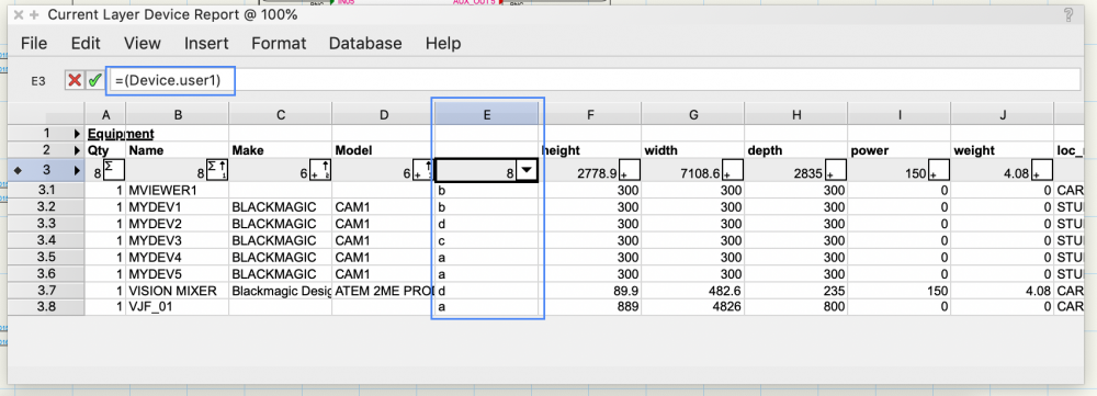
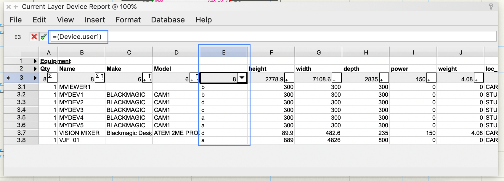
Hi Dmitry
Here's an example: I've enabled a custom Device field, given the Devices on my schematic some values for the custom param, and created a Device Report. Then I inserted a column of my own into the Report, enabled View > Database Headers and added the formula '= (Device.user1) and recalculated. Then the values appear.
Best
Conrad
-
2
-
-
Ok, got it this time! Sorry for being slow on the uptake 🙂 I'll look into that. Thanks for taking the time to spell it out.
I had a thought some while back to allow Circuits to be drawn anyhow and flip them afterwards if they were IN -> OUT. I remember that flipping the Circuit was not a completely trivial exercise. Leave this with me.
Conrad
-
Did you know...
that double-clicking with the Connect tool makes the "next connection"? Say you're connecting some sockets on device A to device B. You take the Connect tool and draw your first Circuit joining the topmost socket on A to the corresponding one on B. Your Circuit remains selected after creation - here's why. If you now want a similar shape of Circuit from the socket below, just double-click it.
This is the 2020 version of the old Connect Next command. And it's even better than before - it's smart about signal types too. So start double-clicking and save yourself time!
-
1
-
-
Did you know...
that ConnectCAD 2020 works nicely with Vectorworks Project Sharing? This is a happy by-product of our transition to Vectorworks SDK!
So when you have more than one designer working on your project, set it up for Project Sharing and you can all work together on the same file.
Give it a try!
-
1
-
-
Did you know... How to do Arrow connections between layers?
You select the Connect tool, choose Arrow mode, click on your source socket and you want to move to another layer. How?
2 ways:
Use the Navigation Palette - click in the active layer column to switch layers, or...
Use Cmd (Ctrl)-Arrow-Up/Down keys to move up and down the layer stack.
Either way it always helps to have the Nav Palette open so you can always see where you are going 🙂
-
1
-
-
Hi Everyone,
This topic is a place where I will share nuggets of information and techniques you may not have come across.
Conrad
-
3
-
-
Hi Ean
When you say "logically listed" are you able to say what the logic is? IMO a simple consistent rule would be better than adding flipping options. That's what I'm trying to get at.
Label text changing position is a bug and we have it fixed.
Conrad
2019 vs 2020 changes
in ConnectCAD
Posted
Thanks Danny
I will extend the range to GIANT RACKS