JBenghiat
-
Posts
2,016 -
Joined
-
Last visited
Content Type
Profiles
Forums
Events
Articles
Marionette
Store
Everything posted by JBenghiat
-
The simple answer is, yes, this is definitely possible. Also, we're assuming you mean a Spotlight Lighting Device object and not a rendering spotlight. (Both are possible). You would use vs.CreateCustomObject() to insert a Lighting Device at the desired location and orientation, vs.HMove3D() to set the z location, and then set the Lighting Device fields for pan, tilt, and which symbol to use. The least straightforwards element is mapping the key value (e.g. "D") to the name of the symbol you want to use for the lighting device. You can hand-code a dict, read from a worksheet, attach a record to the symbol, etc.
-
VS does not have the ability to delete or rename a field. I suspect Sam is correct -- the only solution is brute force: - Rename the old record - Create the new record - Attach the new record to the same objects as the old record - Copy all data from instances of the old record to new - Iterate over all text object in symbols, and re-link to the new record - Delete the old record The following object variables can help you work with linked text: ovTextIsLinkedToRecord = 680; // Boolean, read only - Public for VS ovLinkFormatUsed = 1350; // InternalIndex - the RefNumber of the format this links to ovLinkFieldIndex = 1351; // short - the index of the field of the format used
-
The VP cache just literally contains the lines and polylines that make up the hidden line render. If you're annotating by the physical appearance in the VP (e.g. object heights), this could work, but you won't be able to access the drawing objects. Data tags use some special code that's not available in VS or the SDK. My guess it that the attachment tool is using the VP view and visibility settings to query objects in the corresponding design layers.
-

Symbol with newly attached Light Info Record causes VW crash
JBenghiat replied to dpkolus's topic in Entertainment
@mjm My point was not that Vectorworks won't crash, but that I often hear users who think they did something wrong, or have a computer that's not up to spec, or too many browser tabs open, and don't report the bug. In my experience, crashes that are consistently reproducible and have test files and either detailed steps or videos attached get resolved fairly quickly. While VW does get crash reports from Apple and MS, there's usually not enough data in the report alone to diagnose and fix the bug. -
Symbol with newly attached Light Info Record causes VW crash
JBenghiat replied to dpkolus's topic in Entertainment
- Vectorworks should never crash, even if a user does something incorrectly, so you should report this as a bug, attaching your file and providing instructions how to reproduce. https://www.vectorworks.net/support/bugsubmit - The Light Info Record only sets Lighting Device default data, so unless you want to change the data in existing Lighting Devices, you don't need to take any further action. The symbols should be available to add to the summary as soon as you attach the LIR. - Lighting Symbol Maintenance, under Spotlight>Reports, makes managing the LIR a lot easier. It helps ensure you don't enter bad data (which could be your issue), and has an option to push out any changes to existing Lighting Devices. -
The layout items are all plug-in objects; insert a static text item and then change it's type to the desired item. Note, you are building more of a connected tree than a visual layout, a lot like marionette, so what you see in the VW document looks nothing like the resulting dialog.
-
Spotlight is changing fixture types to c clamp - super non-productive
JBenghiat replied to mjm's question in Troubleshooting
Or more specifically, the OIP configuration saves with the file. The setting in Preference will also become default for the subsequent new file. In most cases, I'm dealing with one of two scenarios: I have a house inventory, and no one is dealing with clamps in the paperwork, or I have a production electrician in charge of pulling iron, and then they're using a separate "Iron" field in LW and not an accessory in VW. Either way, I don't want clamps to show up as accessories. I also don't really care about seeing the right hanging hardware in 3D, as long as the distance below the pipe is correct. -
Script to Select all Fixtures of Instrument Type on Truss
JBenghiat replied to spettitt's topic in Vectorscript
Just thought I'd mention, in addition to the solutions you can find in AutoPlot, Savvy Select Similar Instrument will do this as well https://benghiatlighting.com/software/product/savvy-select-similar-instrument-3/ -
I figured out the issue. buildvwr.exe requires the 64 bit versions of msvcp100.dll and msvcr100.dll, which aren't included in Windows 11. I was able to grab copies from a wine install, and now the build functions without error. I'll attach here if anyone else runs into this issue. msvc*100_dll.zip
-
Spotlight is changing fixture types to c clamp - super non-productive
JBenghiat replied to mjm's question in Troubleshooting
@mjm I'll add that your Object Info seems to be using custom parameter settings, and is out of date. The standard configuration has "Edit Cell" and "Edit Accessory" dropdown menus under Instrument Type, which would make it more clear that you have the light's accessory selected. -
Simple script to enable/disable Spotlight Auto-Position
JBenghiat replied to spettitt's topic in Vectorscript
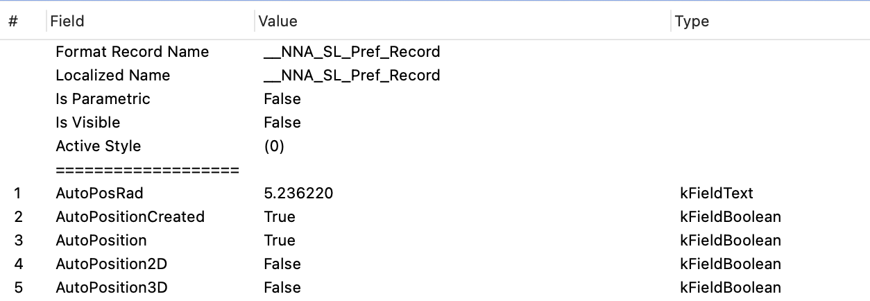
It's a hidden record. Get a handle to the record format via it's name. It's possible that the values get loaded into memory, so changing the stored value may have no effect.
-
Spotlight is changing fixture types to c clamp - super non-productive
JBenghiat replied to mjm's question in Troubleshooting
Your symbols are constructed with your clamps as accessories (this is how they default now, and I'm not in favor if this unless you're pulling a complete shop order). When SSS turns blue pre-selection, it's letting you know that you're hovering over an accessory. You're not changing your Lighting Devices to accessories; what you're seeing is the tool selecting all the clamps for you and setting that as the active component to edit in Object Info. Either remote Light Info from the clamp in your lighting symbols, or be careful where you're clicking. HTH -
Selecting Lighting Devices by Channel Range
JBenghiat replied to MeTheMachine's topic in Python Scripting
Check out AutoPlotVW. This is just one of the many useful commands you can find in its roster. http://autoplotvw.com Criteria can't accept a list of options. You can parse the input string, and if it's in the format (\d+)-(\d+), construct criteria that links something like: ((('Lighting Device'.'Channel'<='103') & ('Lighting Device'.'Channel'>='101'))) but that won't handle non-contiguous ranges the way AutoPlot can. Unless you want to develop the script for learning purposes or as a step for a more complex script, AutoPlot will be well worth the potential hours spent. -
There's an SDK. The documentation is out of date and incomplete, but the examples in the SDK download are current. https://developer.vectorworks.net/index.php/SDK
-
I've had to re-install Windows, which meant updating to 11, and now I can't get buildvwr.exe to run without error. I have a few questions: - Is the .vwr the same for Windows and Mac? If so, I can just copy from the Mac install and avoid this issue - Looking at a previous .vwr built with the Windows script, it appears to be a zip file. This seems to be contrary to the information in the developer wiki, which states the .vwr is just a directory with an extension (which is definitely true on Mac) - If the answer to my first question is "no," has anyone encountered this and figured out a solution? As a side note, I've eliminated the buildvwr step when compiling on Mac, and used a Copy Bundle Resources step, which both copies the .vwr and sets any needed permissions and flags.
-
The script needs to actually hide the objects, as opposed to turning them off. Vectorworks allows you to set the visibility of individual objects, but as viewports have mostly eliminated the need for this, it's only accessible via script. Here are two one-line scripts to hide and show all lights. Hide((INSYMBOL & INOBJECT & INVIEWPORT & (T=LIGHT))); Show((INSYMBOL & INOBJECT & INVIEWPORT & (T=LIGHT))); Hiding objects has some caveats -- for example, a hidden object can still be selected, causing unpredictable results with some commands.
-
Two things are happening: 1. Your drawing is not as accurate as you think it is. Change your units to a decimal precision of .001, and you'll see that your extrude dimensions are rounding to the nearest mm in Obj Info. 2. GetSymLoc3D is getting the translation of the symbol's transformation matrix. For objects with a 3D rotation, this seems to take the layer elevation into account. For unrotated objects, it does not. That could possibly be a bug. In order to get the correct location: - Use GetSymLoc3D() for the z only. Use GetSymLoc() for the x and y - Use Get3DOrientation to get the axes rotations. If the x or y is non-zero, the z will have the layer elevation included in the value. Adjust accordingly.
-
Store All Symbol Names in Resource Manager To Popup OIP
JBenghiat replied to Steven Morgan's topic in Vectorscript
Are you aware of the VectorScript function reference? https://developer.vectorworks.net Symbol() won’t help you at all — it places a new symbol in then drawing, and does not accept a criteria as a parameter. If you want to use criteria, I think Eval() should work. You need to get the handle of the resource in the list, check if the record is attached, and if so return the name, otherwise return an empty string. Otherwise, the check involves getting the number of records attached to the symbol, getting a handle to the record by index, and checking if the name matches. For a function to return a value in VS, set the name of the function to the value (you are not returning anything here). Also, your while loop will stop as soon as you a counter a symbol without your desired record attached. Instead, consider getting the number of resources in the list and using a for loop. -
Renderworks is incorrectly rendering projected images (which includes shutter cuts) for render lights with wide Beam angles. I've had this confirmed as a bug. I believe it was introduced in SP2 or SP3. Shaded and Redshift behave as expected.
-
Store All Symbol Names in Resource Manager To Popup OIP
JBenghiat replied to Steven Morgan's topic in Vectorscript
You also want to be doing any pop-up modifications during the widget prep event, otherwise you're going to fill the widget on the first run per Vectorworks session, as opposed to having it refresh every time you activate the OIP. -
Just flagging some cross-nomenclature here. @Sam Jones, you're referring to multiple emitters in a lighting device symbol definition. In this case, you're only going to have one render light per cell in the profile group that masters each set of emitters. (You do need to check for multiple lights for multiple cells). @Jesse Cogswellis referring to the emitter properties of a light object that allow it to behave more realistically.
-
It depends what you want to do with the light. The light that appears in the Viz palette is in the profile group of the object (which is true for all PIO’s that appear in Visualization). This is what allows you to edit the light via Viz and have the modifications persist. (That is, the light doesn’t redraw of every regen). You start with getting a handle to the profile group and then iterate through the objects until you find the light. There’s also a light that gets placed inside the object geometry. Due to a myriad of reasons, this geometry is not so easy to parse. Do some exploring with Debug List View. If I remember correctly, the geometry is in the aux list, which means you can access via Python but not VS. But depending on what you are doing, you may not need to access this light.
-
Agreed -- the rectangular PIO UI is a little wonky. The simple answer is no-you can't eliminate one of the modes in vs/python. You can, however, create a separate custom tool for placing the object. If this is for your own or internal use, just have the tool draw a rectangle, then place and size the PIO accordingly. (Note that for box-type PIO's, regardless of the insertion procedure, the origin is still the left-center). If you want the PIO to always be associated with the tool, see here: https://developer.vectorworks.net/index.php/VS:Similar_Objects_Creation This will cause the tool and PIO to behave as one object. Coding the clipping in vs may be a little challenging. You can set the PIO to have a profile or path group, with you then use to find the intersection. I'm not aware of a way to have VS select the face of an objet, which is what you need to automatically create the shape that goes into the profile group. Again, if this is for internal use, your best route might be to writer a menu command or venture into event-enabled plug-ins to add a button in the PIO that uses the selected object as a clipping mask. You would first have to use the extract surface tool to extract a 2D shape you want to use for clipping. The other strategy would be to add four control points at the corners of the diagonals and use those to set the end points.
-
Turning off all the lights won't turn on the default light. @Pat Stanford's suggestion will work -- if all the light-generating objects are in a hidden layer or class, Vectorworks will create the default light. If you're working with Lighting Devices and still want to see their geometry, this isn't really a viable solution. I recommend replicating the default light. Go to the Visualization palette, activate the Light tool, and place a Directional light (the first mode, that looks like a sun). It can go anywhere in the drawing. In Object Info, deselect the Cast Shadows option. Use @markdd's suggestion to turn all the other lights off via Visualization. While the light won't adjust to your view like the default light, which is always over your left shoulder, it works pretty well for general illumination.
-
For Python you are creating a standard import file or module, and the rules are a little different. I think the python form includes some relevant posts. For VS, create a vile with the extension .vs, .vss, or .px. px files will include and encrypt themselves for locked plug-ins. They also work for unencrypted plug-ins, so that's what I tend to use. The syntax is {$INCLUDE filename.extension}. You can see more in the Vectorscript Language Guide: https://developer.vectorworks.net/images/7/72/VectorScriptGuide.pdf If no path is provided, Vectorworks will look for a file in the same directory as the calling script, which if called from a plug-in, will be in the plug-ins folder. You can also include an absolute path or a valid POSIX path (including relative paths) to access the include file anywhere on your system.