


Kevin McAllister
-
Posts
5,158 -
Joined
-
Last visited
Content Type
Profiles
Forums
Events
Articles
Marionette
Store
Posts posted by Kevin McAllister
-
-
Ok, it turns out this bug has gotten even worse. Now if you change the scale of a viewport it jumps to the centre of the page too 😟
@Andy Broomell is it doing this for you too?
Kevin
-
38 minutes ago, Andy Broomell said:
I occasionally uncheck this when the grayed objects are indecipherable, or if I'm trying to see a Bitmap object that's outside the Group.
Good tip. I often switch to wireframe. Snaps are better as is clarity. Rendered "greyed" objects are pretty much useless in my experience.
Kevin
-
Bumping this.
@JuanP or anyone at Vectorworks, will this bug ever be fixed? It costs a lot of time in realigning viewports.
Kevin
-
 1
1
-
-
Bumping this wish. Navigation should not be tools. So basic. Every other 3d program I have now subscribes to this theory except Vectorworks.....
This wish was EIGHT years ago.
Kevin
-
 4
4
-
-
Hello,
I've recently noticed some issues rendering soft goods in shaded rendering mode. Its of concern because drawings now show incorrect information or some soft goods are missing entirely. Here are some examples -


Wireframe and Shaded side by side in the design layers. Note some soft goods don't display all the way to the top and ones set to Simple 3D disappear completely.
Similar issues show up in sheet layers. They improve slightly when I dial up the sheet layer resolution but this isn't really a practical solution for file size. I've attached a PDF.
Are others seeing these issues? I most often use the Simple 2D and Simple 3D options when drawing softgoods to indicate goods hung flat without fullness. @C. Andrew Dunning this may also be occuring with your tools.
If others are seeing this too I'll file a bug.
Kevin
-
2
-
-
Thanks for the followup.
I checked the polyline at the time an it seemed ok. It looks like I deleted the offending object. If I see this again I'll file it as a bug.
Kevin
-
Has anyone else seen this type of display anomaly recently, where a 2d polyline displays differently in Top/Plan and Top views? This is the first time I've seen it and it remained even after pasting into a clean file which leads me to believe it may be a bug.
Kevin


-
5 hours ago, VIRTUALENVIRONS said:
I am leaving for the afternoon shortly, tomorrow I will make a short video. You want believe how easy it is to make our own, big small, fat, flat, etc.
I would love to learn. I have used C4D to make things like flags in the past. My license is quite old (R18 I think) but its still a useful tool.
Kevin
-
3 hours ago, VIRTUALENVIRONS said:
I made those in C4D. I think you are a C4D user also, is that correct? It only took five minutes to make all the rocks. The longest part was exporting them. Pat Stanford put them all in one file, the first set.
These are great. Thanks for sharing them. Were they procedurally generated?
Kevin
-
19 hours ago, Tony W said:
I have Architect and for the life of me, cannot work out how to outline a line. Im Adobe Illustrator there is a command that converts lines to an outline. For instance, if I am drawing 5mm wide line x 20mm long line, illustrator will convert it to a 5 x 20 rectangle where I can amend the stroke thickness.
I have used Benson's solution in the past. You could also switch to the double line tool if you need to do this regularly.
Kevin
-
1
-
-
3 hours ago, MartinBlomberg said:
No clue about that unfortunately.
Check your direct messages. I sent you a 3d model. This tent is likely an S5000 given the size.
Kevin
-
2
-
-
It's almost certainly from Tentnology or Warner tents. Here's the Tentnology webpage - https://www.tentnology.com/our-tents/brands/saddlespan-tents
I've worked in these tents extensively. They hold the patents. @bcd there is an edge truss that holds it taught around the curve. Its assembled closed like a clam shell and then the top side is pulled over into the open position using a crane or tow truck. The tensioned skin plus a safety cable keep the trusses in place.
Kevin
-
1
-
-
On 7/19/2023 at 4:53 AM, MartinBlomberg said:
Hey all!
I'm trying to draw a 3D stage of a 2D drawing I got for a stage. I've put everything in order in 3D with a 3D locus, just like I saw @markdd do on one of his videos on YT (So educational!). But, I can't figure out how and where to start.. any thoughts or tips? I've tried the Nurbs-curve but I guess I'm too bad a using that tool since I can't get it right 😃
Looking forward to hear your thoughts on this! The 2D Drawing is attached here.
Many thanks! Martin
Who is the manufacturer? Do you know the model?
Kevin
-
I store lots of information in my VW file so it's easily accessible. Large files can be an issue but I usually just make a file copy and purge the extra information if the file needs to be shared. I haven't found the large files to be a problem for my own use and hard drive space is cheap.
Kevin
-
I still see it happening once and a while. Usually saving and closing the file and then re-opening it solves things.
KM
-
I would make an extrusion of an array of oversized boards (too much thickness) and make a contoured surface. Solid subtract the two and extract the resulting board faces that are now contoured. Finally I would use shell to give the board faces thickness following their new contour.
If you prefer using NURBS for part of the process, use them to make the contoured surface and use Solid section instead.....
Always a few approached to things in VW.
Kevin
-
1
-
-
3 hours ago, bcd said:
There is.
Instead of importing the PDF / image reference it in by clicking the Reference checkbox on the import window. Then when it's updated you can update it your drawing by right clicking Reference in the Reference tab of the Navigation Palette.
Of course. I should have thought of that. So really its an interface wish then 🙂
Kevin
-
2
-
-
- Popular Post
- Popular Post
I wish there was an option to right click on an image (or even PDF) in a document and have an option to replace it with a new image. The idea being that images often get resized or cropped, so by using replace the new image would be scaled or cropped automatically by replacing the old image. So often clients request variations or send new graphics to be incorporated and this workflow would help with efficiency.
Edit - images/pdfs should also have their filename retained somewhere in the "bitmap" or "PDF" object they become so you can easily track their source.
Kevin
-
8
-
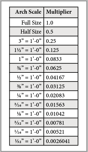
FYI this is the scale multiplier chart I shared with Adam in our message exchange..... I usually scale the object before exporting to STL and then undo.
KM
-
1
-
 1
1
-
-
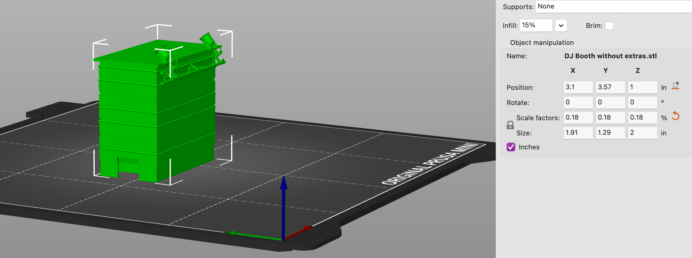
13 hours ago, AdamParboosingh said:
Thanks all.
If I'm reading the replies correctly, this still requires me to scale the object down on my own. Either through scale object in Vectorworks or through the Slicer object manipulation window, this makes me need to figure out the height of the scaled object in reality or proportionally change the size in the Slicer.

Yes, likely. Years ago I wish-listed a way to output scaled objects to STL but that wish was never implemented. If you don't want to do math, then create a sheet layer viewport in the scale you want to print at and then dimension the object to the extent of its bounds on the sheet layer itself. This will give you a size dimension to input into your slicer to print at the correct size. I check print size this way all the time.
Kevin
-
4
-
-
4 hours ago, EAlexander said:
I approach this kind of thing with Hybrid Symbols.
^ this definitely. My symbols often start out as just 3d but usually become hybrid at some point......
Kevin
-
1
-
-
I think I would make each artwork a symbol with an attached description record. Then you could easily label them in any view with a data tag that pulls the description from the record. It would take some initial time to input, but then it's fairly easy to maintain.
Kevin
-
2
-
-
Just now, Andy Broomell said:
For me, auto-generated classes are typically coming in from symbol libraries via the Resource Manager.
^ this. Ideally when adding a symbol from the library added a class VW would ask if I'd like to use the symbol's classes or assign them to my own.
Kevin
-
1
-
-
4 hours ago, Andy Broomell said:
Is there anyone that desires a class called "Furniture-Main" (for example) and actively uses it?
This made me laugh out loud. I hate that class 😊 only because I move things out of it all the time. When something doesn't show in a sheet layer viewport, its usually in an autogenerated class and I've forgotten to move it....
Kevin
-
3
-


Convert objects made of 3D polygons to solids?
in General Discussion
Posted
@Benson Shaw is right that the file would definitely help us propose solutions. I think I would try extracting the front face as planar surfaces, using the face mode of the Extract tool, and then using Add Surface to join everything together into one surface. From there you just extrude the surface. If you want to remove the facets around the opening you could go back in and edit the polyline (Command [). This gives you access to the cutouts which you could redraw using circles and squares combined with Add surface.
(Everyone should learn about editing polylines with Command [. It's very useful.)
Kevin