J. Wallace
-
Posts
702 -
Joined
-
Last visited
Content Type
Profiles
Forums
Events
Articles
Marionette
Store
Everything posted by J. Wallace
-
@Benson Shawre:units. In Canada we drift back and forth from imperial to metric measurements. Keeps us on our toes. Survey data was in imperial...sometimes it's in metric one never knows. Thanks for all your help.
-
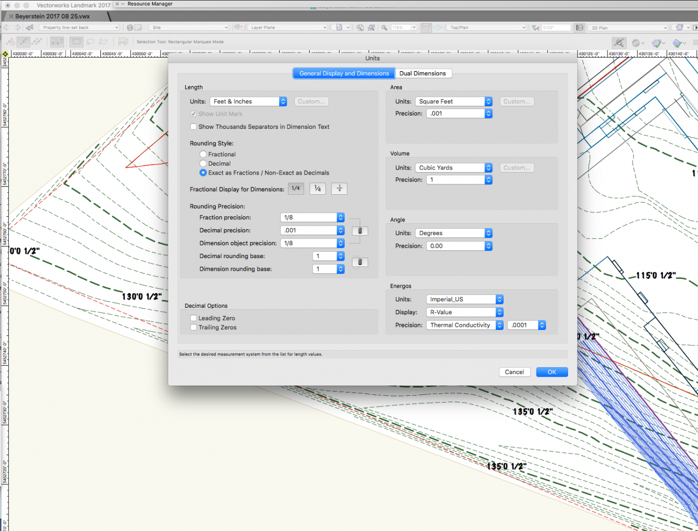
Yes I figured a work around @Benson Shawthanks. For some reason if I switch units from feet to feet/inches I have to disable fractions in the rounding precision box or my contours have the 1/2" added to their readings. Really appreciate your help. It seemed my week was full of new site models for propject start ups, and you really helped out. Thanks very much.

-
I switched units during my workflow and the site model has now changed again to show fractions. Not sure why this is showing contours with an added 1/2". Is this a bug?
-
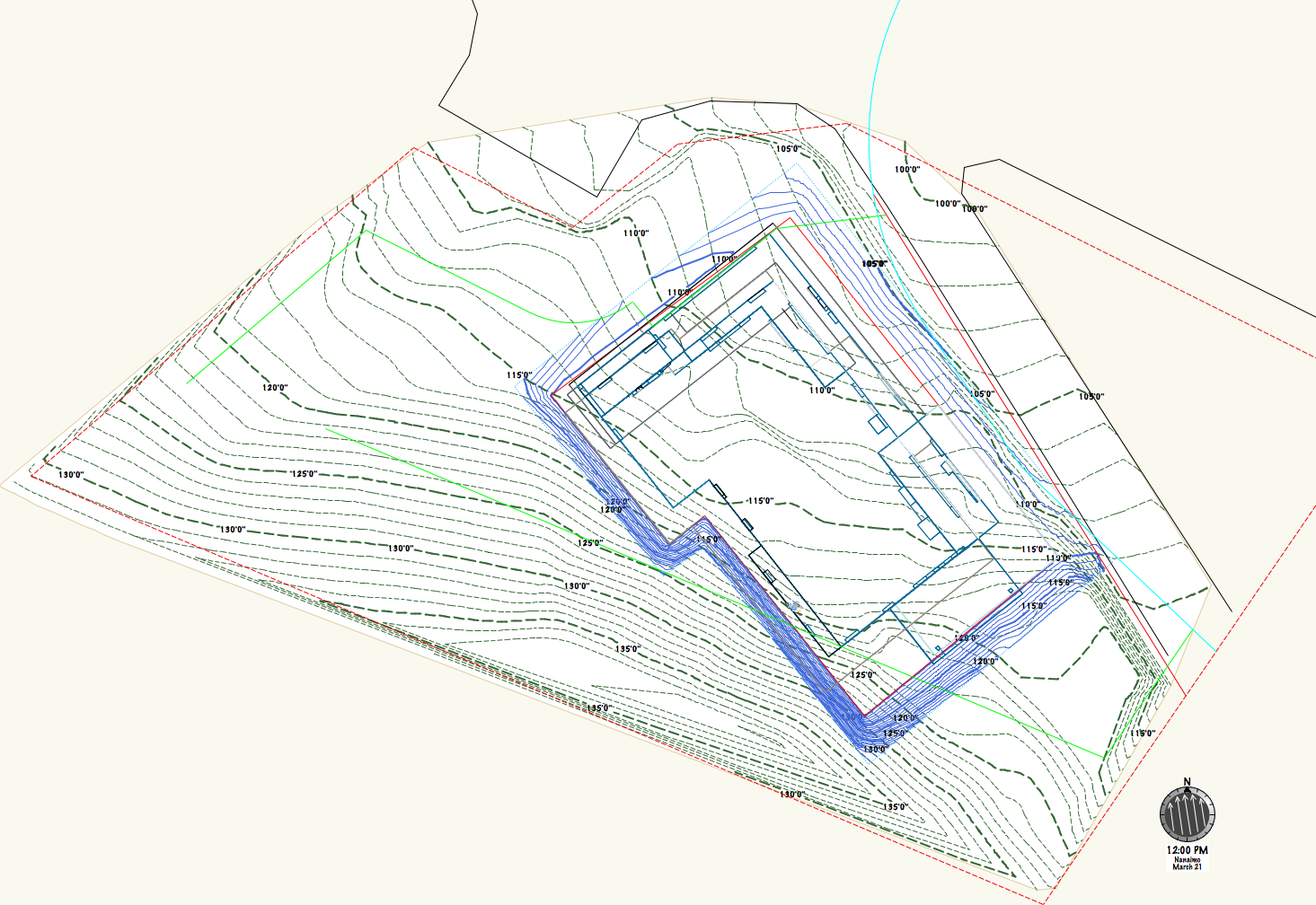
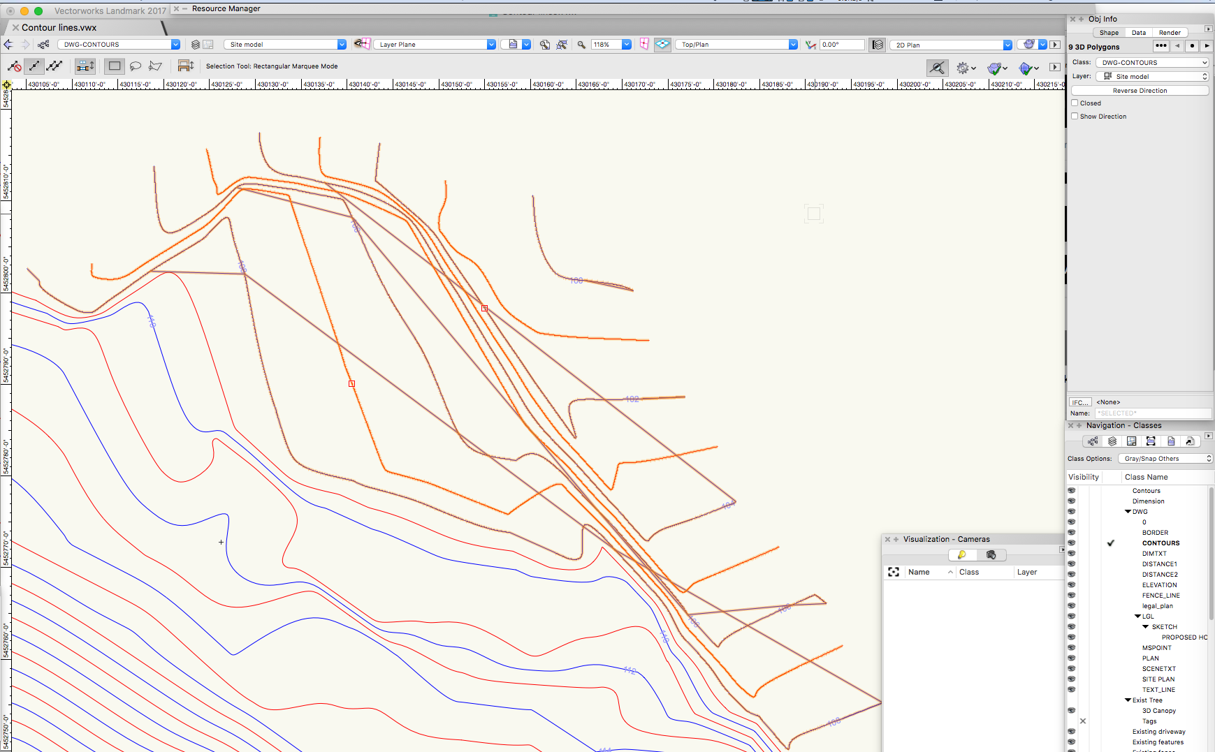
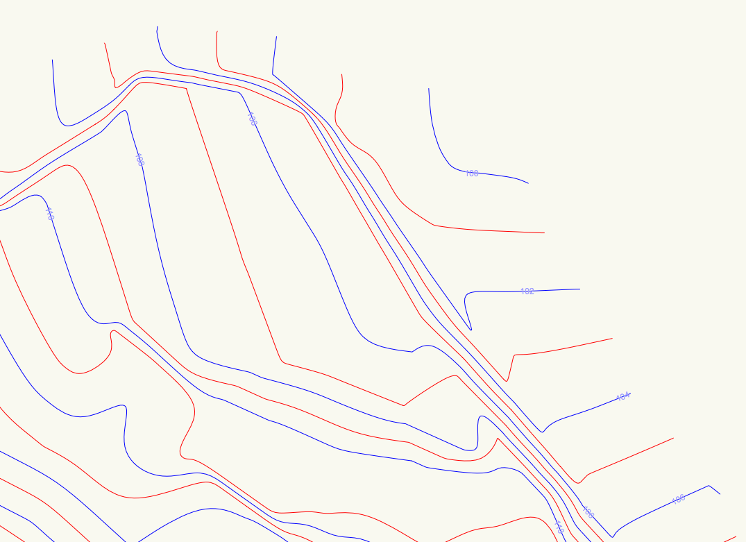
HI everyone It seems to be site model challenge week. Previously had a challenge creating this site model, seem like the contours now have a fraction assigned to them as shown in the image, site model settings are also shown. Has anyone seen this before? I'm sure there is an easy fix. Thanks ps just fixed this...it seems when you edit the label position that it will change the label appearance (fraction, decimal or not) based on your units setting. This seems odd to me as this is a first...


-

Polylines conversion not working as expected
J. Wallace replied to J. Wallace's topic in General Discussion
@Benson ShawThanks very much. The dwg export import did the trick. I thought I was going to have to trace all the contours, happy to see this worked. When converting to NURBS I had three polylines fail to convert, I replaced these and viola...Thanks again Benson.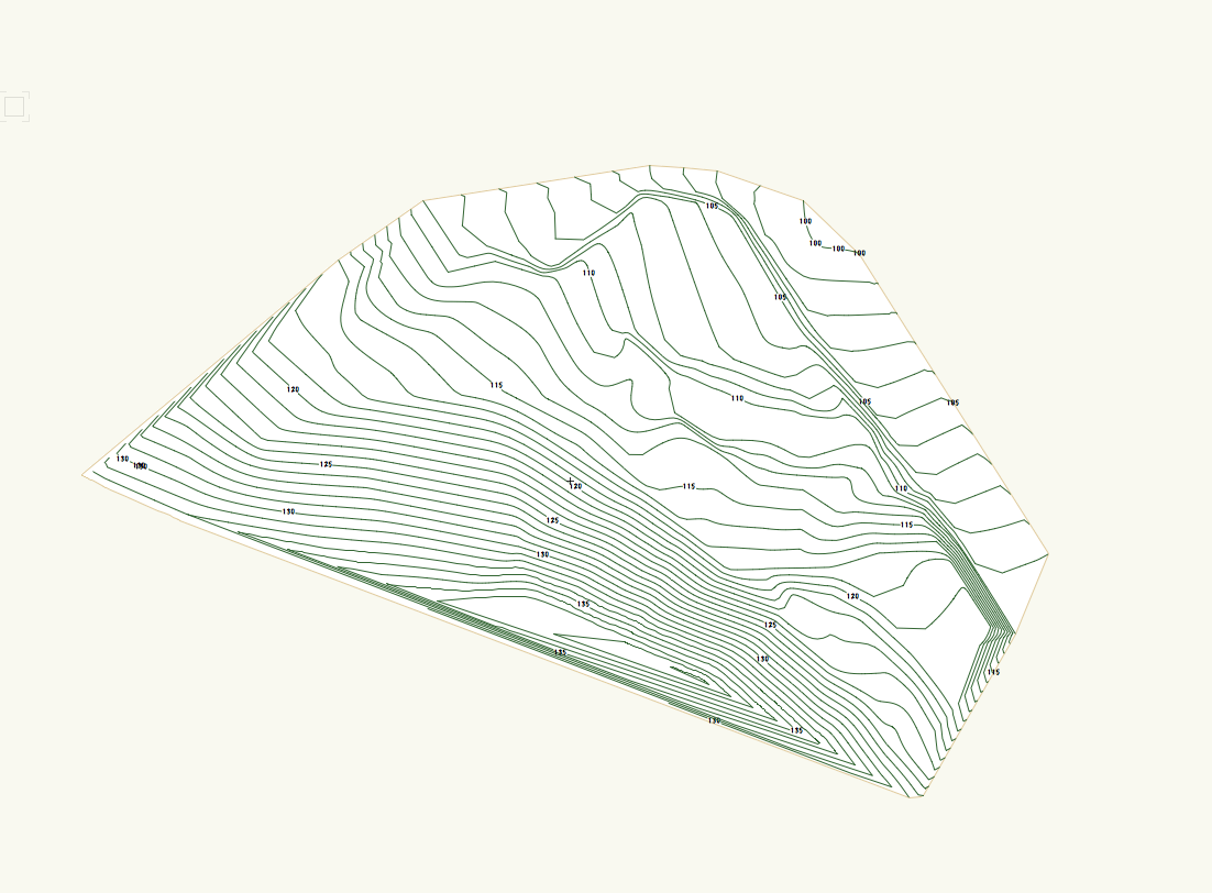
-
Hi @zoomerYes I can combine these after they have separately been created. I don't seem to be able to create a single site model using 3d polys and stake objects. It's all good now. Kind of a funny model in that the data I received was mainly around the building area. Thanks for your help.
-
Polylines conversion not working as expected
J. Wallace replied to J. Wallace's topic in General Discussion
Another screen shot selecting just five of the polylines and converting them to NURBS or 3d Polygons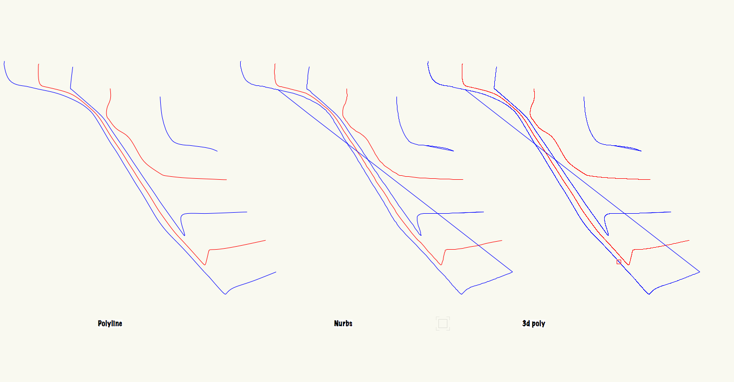
-
Creating a site model from a .dwg file a surveyor sent. I had to join a few polylines to make sure that each labelled contour was one unit. When I go to convert these polylines to 3d polygons or NURBS I get the following results. I've not seen this before. Any thoughts would be very helpful. If I trace a new polyline it converts as expected. Thanks in advance for any help. ps in the after image you'll note that I selected and converted only a few of the polylines.
-
No idea why this was misbehaving @Benson Shaw. I have attached an earlier version of the file for your interest. When I look at each site model there is only stake objects in the one and 3d polys in the other. Pretty bloated file thought...When I start a new drawing I use one of my templates, perhaps this is the culprit. site_model_sample.vwx
-
@Benson Shawcombing the source data worked after one set was used to create the model. Odd that adding two different types of source data does not allow for site model creation. Thanks again to both of you.
-
Thanks @Benson Shawthat worked very well. Hadn't thought of that. Thanks again. Strange behavior from the site model when your trying to create a model using both stake objects and 3d contours...definitely doesn't like dealing with both at one time. Thanks to Benson and @zoomer
-
Hello all Just wondering if anyone has come across this, I'm wondering if you can join two seperate site models. The top one was formed with stake objects the bottom from contour lines. When I tried to initially create one model with these two different items (stake and 3d poly) it would not work. I have attached the information I working with. As a workaround I could use the spot elevations with the contours? Thanks


-
Never new that existed, thanks @Benson Shaw
-
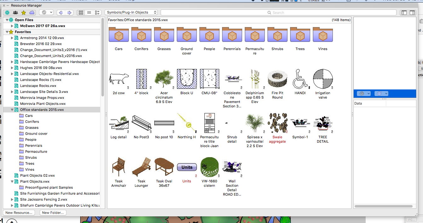
@thoblynI have built my own file which I called office standards. It sits on my desktop and is placed as one of my favorite files within the resource browser. You have to initially assign the plant data to each individual symbol you create but once your there you can store it for later use. Learned this trick on one of the Landmark podcasts a couple of years ago. Works for me.
-
I've been hoping for years to see the plant symbol gradient colour issue fixed when grouping plants who have gradient colour within their symbol. It would be great to have the option of using one colour vs the results that we currently get where one plant in the grop has a different/lighter colour.

-
Thanks for the tip @bcdThat's great to know.
-
Call out arrow/starting point not editable after placement
J. Wallace replied to J. Wallace's topic in General Discussion
Yikes, I thought or was hoping that this would be simple. That did the trick, thanks very much @Andy Broomelland @Pat Stanford -
Call out arrow/starting point not editable after placement
J. Wallace replied to J. Wallace's topic in General Discussion
Thanks Pat. Unfortunately it didn't fix this issue. I appreciate your help though, thank you. -
Call out arrow/starting point not editable after placement
J. Wallace replied to J. Wallace's topic in General Discussion
HI @Pat Stanford Thanks for that. Is this the fix/thread that you are referring to? -
Hello everyone Over the past week I've noticed that when I place call outs in the annotation layer of a design sheet that the starting point will not longer allow me to edit it's location. As the image shows there is no longer a vertex showing to fine tune or adjust the arrow location. Any help would be appreciated. ps I think this started right after the last service pack.
-
Totally agree...
-
@Alan Woodwell, thanks Alan that fixed it. Strange that the contour would project itself forward like that. Thanks again that was a huge help.
-
Thanks for the reply @Benson Shaw. I checked out that thread, thanks. Also made sure that 'Display Planar Objects' was unchecked. With some further investigation it looks like it's coming from my site model. No idea why? This issue doesn't occur in the other VP which is a reverse angle. Thanks again Benson.


-
Just finishing up a concept and I'm getting strange graphics behavior occurring. The viewport on the left shows a camera view but it looks like some lines from the site model are visible in front of some plants. I've looked through the file to make sure that these are not 2d polylines causing the issue...at a bit of a loss.

-
Thanks Jim, I appreciate it.