

About This File
This is my first marionette and it's based on @Marissa Farrell's image processing!
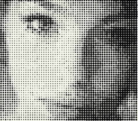
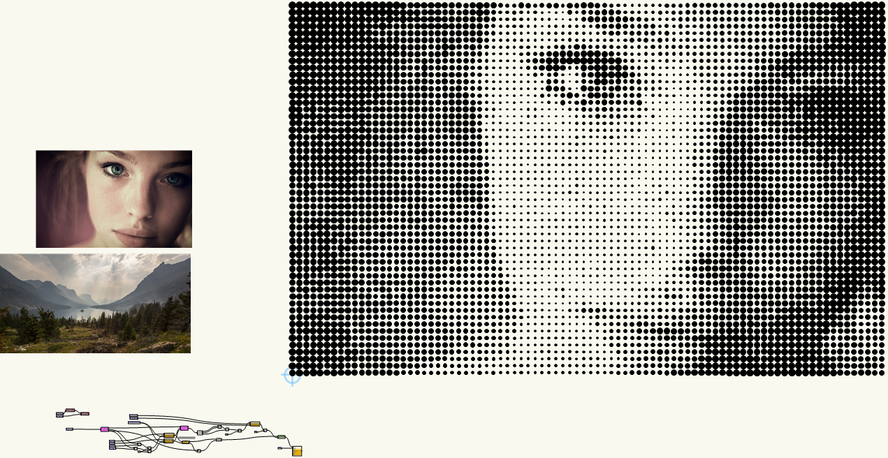
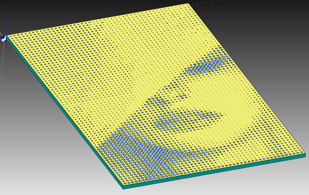
It takes an image and creates a Halftone object of it with black circles:
IMPROVEMENTS:
-
Final objective is that I'll add cnc DXF milling information to this marionette so that it can be milled on a CNC machine.
(We've milled Halftone parts in the past using Jason Dorie's Halftone program http://jasondorie.com/page_cnc.html)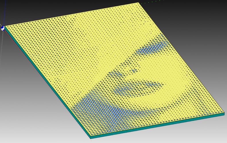
Result: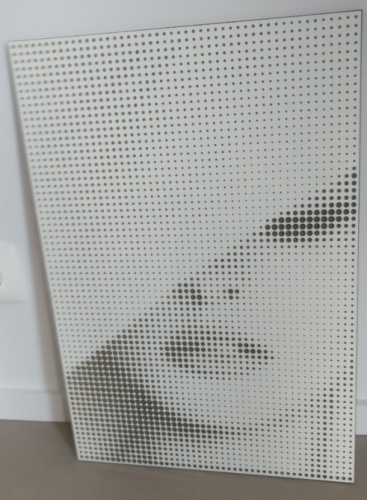
Detail:


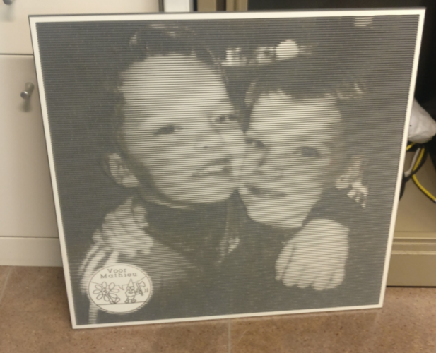
-
Maybe add a line milling. The image below is milled by us in the past with Jason's program.
-
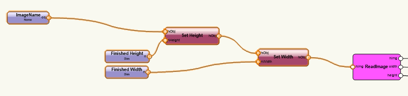
Be able to change the dimensions of the final halftone image. Now it takes the pixel width and height of the image, but I would like this to be some adjustable parameters. Changing the height and width with Set Height and Set Width has no effect. Somebody has a suggestion on how to do this?
-
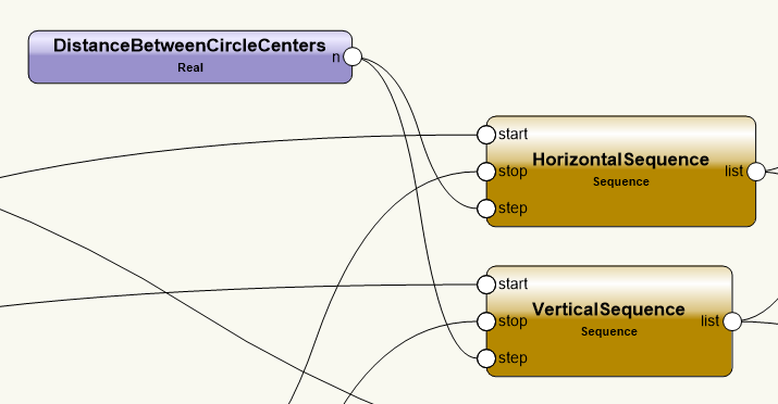
Now the marionette looks at the color of each pixel on a grid with step "Distance between Circle Centers". Related to that color, it creates a circle with according radius on the position of that pixel:

The problem with this method is that that single pixel on the grid has total control on the radius and the one pixel just next to the chosen one has no relevance. A better mechanisme would be that the size of the circle is related to the average color of all the pixels in the area of the square "Distance between Circle Centers"x"Distance between Circle Centers". Anyone with some advice on handeling this? I got some little progress on it:
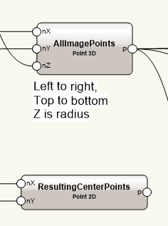
Here we have 2 lists. One with all the pixels. X,Y coordinates of the pixel, Z is the radius of the circle according to the color. The other list has the X,Y values of the centers of where the final circles have to be placed.
Following this we need to check the distance of all the image points to the center points. If this is smaller than a condition, then that point's radius had to be taken into account for calculating the average radius of that centerpoint. Any one has a quick hint on how to create this in marionette?


What's New in Version 1.0.0 See changelog
Released
No changelog available for this version.

Recommended Comments
Join the conversation
You can post now and register later. If you have an account, sign in now to post with your account.
Note: Your post will require moderator approval before it will be visible.